Energy consumption in buildings accounts for almost 40% of primary energy consumption in Europe – about 3100TWh per year. However, a lot of this energy is used for heating and cooling. This proves that better insulated buildings can have a big impact on our overall energy consumption.
Building insulation can be improved through a relatively low-cost retrofit and renovation process. The huge savings potential of these processes also increases the market value of the building.
However, these processes are not based on quantitative insulation data, such as U-values for building structures. In order to obtain reliable and precise data on the U-value of a specific location, it is necessary to empirically measure the U-value of building elements. This article describes three different methods for assessing the quality of a building’s insulation. In addition, it details the heat flux method and its application to a typical Swiss residential building constructed in 1948.
Insulation Quality Assessment Methods Here are three different methods used to measure the insulation quality of a building: Thermal Imaging (Infrared Imaging) This method measures the thermal radiation of an object and produces an image showing areas of low and high radiation. It provides information on the overall quality of building facades, thermal bridges with uneven insulation and sections. The only downside is that it does not produce quantitative data for analyzing insulation quality, such as U-value data. Multiple Temperature Measurements This method is based on temperature measurements inside and outside the building element. By synchronizing these measurements, the heat flux can be calculated indirectly, which in turn allows the U-value to be calculated. Although quantitative data can be derived, this method is difficult to use in most practical situations, as reliable measurements require a temperature difference of at least 10C, which rarely occurs.
heat flux method
A heat flux is created in the material when there is a temperature difference between opposite sides of the material. Heat flows from the hotter side to the cooler side. Based on this principle, the heat flux method can operate and measure the U value of any building material in situ. It is a weiyi method that provides reliable quantitative information about the building envelope.
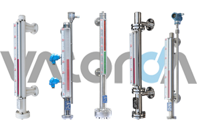
U-value measurement using the heat flux method This case study uses a magnetic flap level gauge for measurement. Measurements conform to ISO 9869, ASTM C1046 and ASTM C1155 standards. The kit includes two magnetic flap level gauges, a heat flux level gauge and a data logger with adjustable measurement frequency. It helps to automatically record heat flux through building elements as well as interior and exterior temperatures. The software in the kit generates graphs of heat flux and temperature measurements, as well as U-values for building components. A schematic diagram of the heat flux level gauge, magnetic flap level gauge and data logger is shown.
The step-by-step procedure for measuring U-value using the heat flux method is as follows:
Mount the heat flux gauge on an indoor surface to protect the gauge from solar radiation, convection and direct heating. On opposite sides of the wall, place the two gauges at approximately the same location where the heat flux gauge is installed indoors, and 2-10 cm from the wall for accurate U-value measurements.
U-values were recorded at a frequency of 1 data point every 0.5; 1 hour. The minimum measurement duration is 72h. Use the magnetic flap level gauge software to analyze the measurement data
The U-value was calculated using the mean value of the heat flux through the building elements and T The building used in the case study has undergone several renovations since its construction in 1948. Renovations included ceiling changes in 1979 and floor renovations in 1999. Insulation materials have been updated and adapted to the respective standards. period.
Two different locations were chosen for the measurements – the exterior wall (A) facing southeast and the floor (B) at ground level. The spot is chosen to avoid adverse effects from heaters, lateral convection and solar radiation. The level gauge is installed at a distance of at least 1m from the heating source.
Results and Discussion The measurement results at point A are shown in Figure 2. The outside temperature at this point is maintained between -1 and 3C, and the inside temperature fluctuates somewhat with the outside temperature and is compensated by the heating system. In the afternoon, when the outside temperature dropped and the inside temperature was heated according to the heating cycle, the maximum heat flux was observed.
Heat flux and temperature measurements at point B remain stable over a longer period of time. It was observed that both temperatures began to drop as the doors to the basement and ground floor were opened. However, when the doors were opened and closed again, the temperature inside the car dropped a few more drops, returning to its original temperature. Measurements for spot B are shown.
In order to measure the U value in accordance with ISO 9869, the temperature difference should be kept above 5 during the entire measurement period. Therefore, in point B, the temperature difference is not sufficient to measure an accurate U value.
Post time: 11-01-22

