1 Overview Electromagnetic flowmeter is a commonly used flow measuring instrument. With the rapid development of modern fine chemical technology, it is more and more widely used in petrochemical, papermaking, metallurgy, environmental protection, food and other industries. Electromagnetic flowmeters are used for fluid monitoring of complex industrial piping systems, real-time monitoring of the raw materials and finished products of the system, and providing a basis for automatic control of the system, and so on.Due to the scattered distribution of electromagnetic flowmeters and the complicated operating environment, its installation process is likely to affect its operating conditions and the probability of failure, thereby affecting the operation of the entire instrument control system. Therefore, it is necessary to analyze the principle of electromagnetic flowmeter, study the installation process, and continuously summarize and update the debugging technology.2 The working principle of electromagnetic flowmeter The electromagnetic flowmeter is mainly composed of a signal converter and a sensor. Its principle is based on Ferrari’s law of electromagnetic induction. A pair of detection electrodes are installed in the sensor perpendicular to the axis of the tube under test. When the flowmeter is connected to a liquid In the medium pipeline, when the conductive liquid material moves along the side of the pipe axis, the conductive liquid moves through the cutting magnetic field to generate an induced electromotive force. The induced electromotive force is measured by the detection electrode, and its theoretical value is: E=kVBd where: E is the induced electromotive force; k In order to adjust the coefficient, it varies with the structure of the meter; V is the average flow velocity of the liquid to be measured; B is the magnetic induction intensity; d is the inner diameter of the pipe to be measured. When measuring the flow rate, the fluid flows through a magnetic field perpendicular to the flow direction, and the flow of the conductive fluid induces an electric potential proportional to the average flow velocity. The induced voltage signal is detected by two electrodes and transmitted to the converter through a cable. After signal processing and related calculations, the cumulative flow and instantaneous flow are displayed on the display of the converter.3 Selection of electromagnetic flowmeter 3.1 Caliber selection When selecting an electromagnetic flowmeter, the selection of the caliber is generally determined by factors such as the nature of the fluid and the flow rate. Generally speaking, when the pipeline flow rate is between 0.5 and 1.5m/s, it is an economical flow rate. If the fluid medium has low abrasion to the sidewall, it is recommended that the long-term flow rate is greater than 3m/s, but should be less than 7m/s. Choose a flowmeter smaller than the pipe diameter. 3.2 lining material selection electromagnetic flowmeter is mainly used to measure the flow rate of fluid substances, and according to the corrosiveness, abrasion, temperature and condensation of the measured substance, flowmeters with different lining materials should be selected. The lining materials and their characteristics commonly used in electromagnetic flowmeters are described below. 1) Natural rubber, its temperature resistance range is -10℃~70℃, abrasion resistance, good insulation performance, and general corrosion resistance. 2) Neoprene, which has better elasticity than natural rubber, is also more wear-resistant, but has poor cold resistance. 3) Polyurethane rubber has a lower applicable temperature than natural rubber, up to -25°C. 4) Compared with natural rubber, nitrile butadiene rubber is more resistant to high temperatures, more wear-resistant, and less elastic, but has very good oil resistance. 5) Polytetrafluoroethylene is a kind of plastic, it is resistant to acid and alkali, but it has poor resistance to corrosion and negative pressure of some abnormal substances such as liquid fluorine, oxygen, ozone, etc., and its wear resistance is also poor. . 3.3 Selection of electrode material The electrode of the electromagnetic flowmeter is installed on the inner wall of the pipe and is in direct contact with the measured substance, so it should be selected according to the corrosiveness of the measured substance. The materials generally used to make electrodes include: titanium (Ti), which is resistant to strong acid; tantalum (Ta), which has high measurement accuracy; platinum-iridium (Pt-Yi) alloy, which has strong corrosion resistance; Hastelloy C (HC), It can be used for the measurement of high temperature hypochlorite, sulfuric acid and nitric acid; 316L, general corrosion resistance, but low price. When selecting an electromagnetic flowmeter, the electrode material should be selected according to the precision requirements of the measurement, the corrosiveness of the measured object, and the price tolerance. 3.4 Other parameter selection The selection of electromagnetic flowmeter should also consider factors such as protection grade, connecting flange and cable. The selection of the connecting flange of the electromagnetic flowmeter should be determined according to the pipeline. Especially for the corrosive fluid pipeline, it is not allowed to perform on-site processing and welding of the pipeline at will, and should be selected carefully.4 The installation of electromagnetic flowmeter 4.1 Preparation for installation Before the installation of electromagnetic flowmeter, its parameters should be carefully checked, mainly to check whether its caliber, lining, electrode and other parameters meet the design requirements. If there is centralized BA control, it should be confirmed and controlled. System compatibility. Before installation, the installed pipeline should be treated with anti-corrosion treatment, and the flange interface should be cleaned. After confirming the flow direction of the measured substance, prepare for installation according to the direction calibrated on the flowmeter. 4.2 The selection of installation position Since the electromagnetic flowmeter is installed on the fluid pipeline, the accuracy of its measurement data is related to the fullness of the liquid substance inside, so when selecting the installation position, the following points should be paid attention to: 1) The flowmeter must not Installed on the suction side of the pump; 2) The flowmeter should be installed in the bottom section of the pipeline that can store liquid, so as not to suck air back and affect the measurement accuracy; 3) When a valve needs to be installed near the electromagnetic flowmeter, the valve should be installed Downstream of the flowmeter; 4) When the pipe drop is large, an upward bend and drain valve should be installed downstream of the flowmeter; 5) When installing an electromagnetic flowmeter, the possibility of bubbles in the pipe should be fully considered and avoided. 4.3 Electromagnetic flowmeter installation and grounding The installation method of electromagnetic flowmeter is generally flange type, and the pipeline can be connected with the matching flange. Before installation, make sure that the purge and pressure test of the pipeline have been completed. Because the electromagnetic flowmeter measures small induced current and low voltage, it is susceptible to the influence of external electromagnetic noise. Therefore, a reliable grounding (cross-over) connection should be made during installation.5 Electromagnetic flowmeter wiring and debugging 5.1 Wiring Before connecting the electromagnetic flowmeter, please confirm that the installation position and direction are correct, and clean the site. Only after there is no dust accumulation, can the wiring be connected. The wiring of the electromagnetic flowmeter includes the connection of the power cord, the input/output signal line, the sensing signal line and the working grounding line. In the above wiring process, attention should be paid to the wiring of the following types of circuits. 1) Input/output signal. Most electromagnetic flowmeters can be programmed and tested through the external PLC, and they can also receive input instructions from the main control system through the communication bus. Therefore, the electromagnetic flowmeter is equipped with signal input contacts, critical measurement value alarm instructions and other access points. The output signal can be connected through the analog point, or it can be combined with the output signal to realize the connection with the PC through the RS-232 communication interface. 2) Sensor connection. If the flowmeter and the sensor are installed separately, a connection is required between the flowmeter and the sensor to pass the sensing current through the measurement terminal of the flowmeter (actually the magnetic pole and voltage measurement unit) to measure each Measure parameters. 3) Ground wire. Because the electromagnetic flowmeter has a small operating current and is highly susceptible to interference from changes in the external electric field, its power supply and signal lines must be equipped with grounding wires to ensure the accuracy of the measurement data and eliminate frequent data oscillations during the measurement process. 5.2 Debugging 1) Inspection and preparation before debugging Electromagnetic flowmeter should be thoroughly inspected before debugging, including cleaning of pipeline debris, and oily medium pipelines need to be dried. The inspection before commissioning also includes the inspection of the electrical circuit. The grounding of the circuit should be tested first, and the test and inspection of other circuits can be carried out after ensuring that the grounding is reliable, so as to avoid the capacitive effect of the circuit, the storage of electricity, or the destructive effect of the measuring power supply on the instrument . In addition, insulation resistance and grounding resistance tests are also required. 2) Water Debugging Whether it is measuring water-based media, suspended liquids, or measuring oily media, before formal commissioning, it should simulate the actual temperature, pressure, flow rate and other conditions of the actual measured medium for water debugging. If an abnormality occurs during the water flow test, or the parameters are missing, the meter should be tested individually or sent to the production unit for verification. 3) System debugging The electromagnetic flowmeter can perform system debugging after the single function water test is completed, and the preparatory debugging of the control host is completed. The oily medium pipeline needs to be dried before the measured medium can be introduced for system operation.When the system is debugged, the host system should perform a code scan on each measuring point in advance to ensure that each instrument component is in a normal working state before performing functional debugging. During functional debugging, the host system reads parameters and critical value alarm tests for each instrument respectively, and then writes control data. Debug one by one, and send the relevant data to the relevant upper computer for analysis.After the host computer has completed the debugging of the various instruments of the system, it can carry out the individual PLC programming and debugging of the instrument terminal. PLC programming debugging is of great significance to instrument debugging. It can read data, write and adjust parameters for a single instrument without affecting the working status of the host. The development of modern PLC technology makes it more convenient to be used in electromagnetic instrument control. Most electromagnetic flowmeters can be purchased with PLC programming controllers that match their products. Through special interfaces, single instrument debugging can be carried out. .After the commissioning is completed, 24 hours of uninterrupted measurement should be carried out under continuous working conditions to observe the stability and reliability of the measurement data, and proofread in combination with other measurement methods, until the electromagnetic instruments of the system can operate according to the design requirements , The pre-acceptance of the system can be carried out.6 Summary Through the application of electromagnetic flowmeters in industrial pipeline control systems, summary of instrument selection, installation process adjustments, tests, etc., have accumulated a certain amount of success in improving the installation and commissioning of electromagnetic instruments in industrial pipeline control systems. Technical experience provides practical experience for a higher degree of integration and automation of industrial pipeline control systems.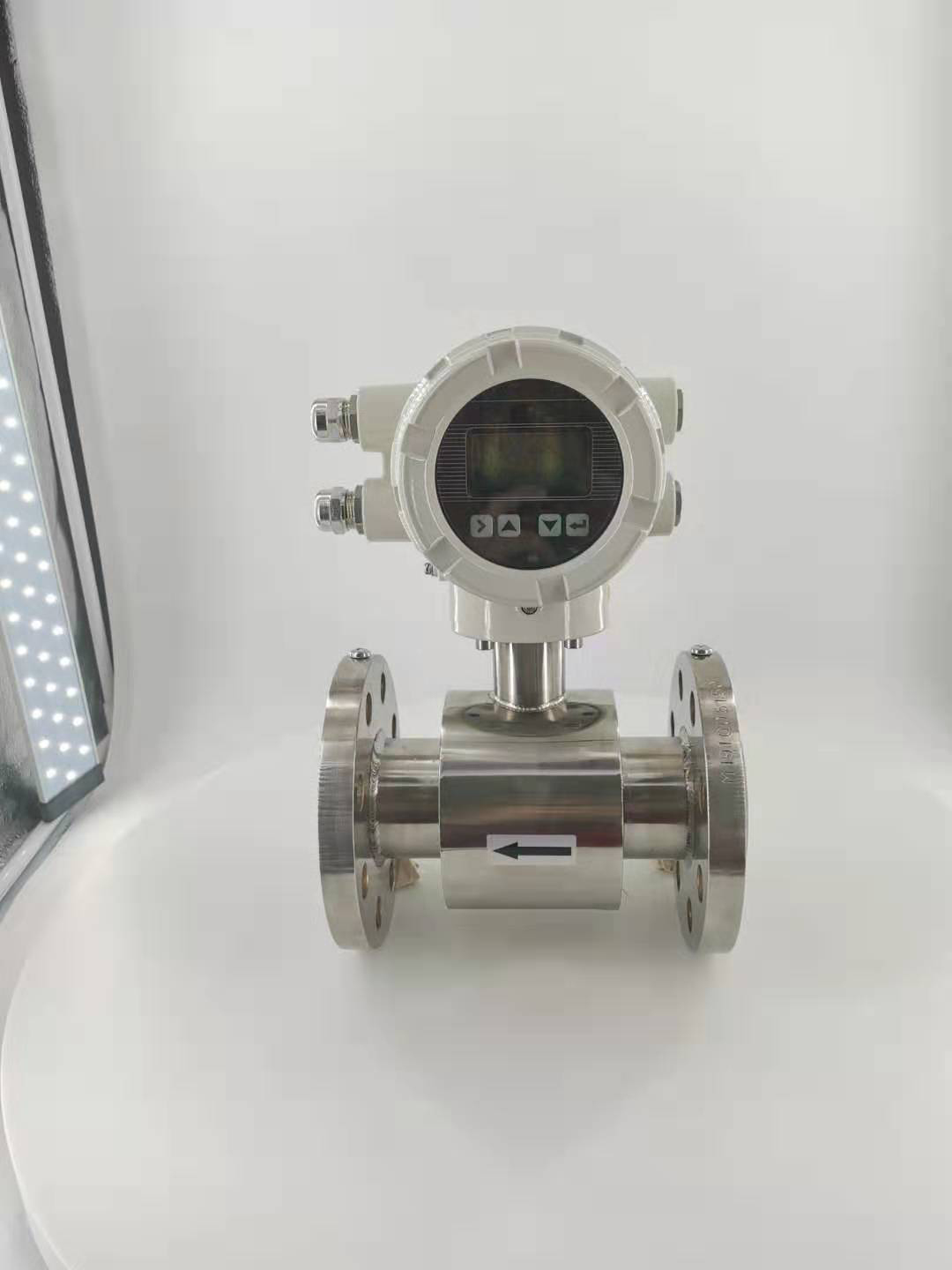
Post time: 21-09-21