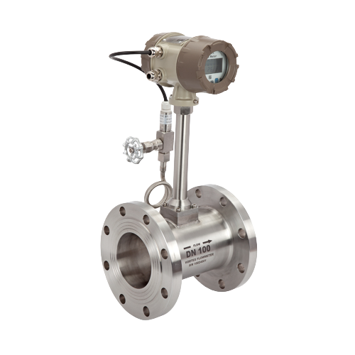
Abstract: This article mainly introduces that when the vortex flowmeter is energized after the installation, there is no actual flow in the pipeline, but the actual data fluctuates on the display of the meter and the cause of the fault and the treatment method.1. After the instrument is energized, the valve does not open, and there is a signal output. ① The sensor output signal of the vortex flowmeter is shielded or there is external electromagnetic interference when the flowmeter is grounded; ②, there are large electromechanical equipment or Electromagnetic interference caused by high-frequency equipment; ③, the installation pipeline of the vortex flowmeter has strong vibration; ④, the sensitivity of the receiving signal of the sensor is too high; For the above faults, corresponding measures need to be taken to enhance the shielding and grounding of external interference. Reinforce the pipeline to eliminate pipeline vibration, adjust the sensor to reduce sensitivity;2. The power supply of the intermittent vortex flowmeter is not cut off, and there is a signal output after the valve is closed. This type of failure is similar to the first type. The cause is mainly caused by pipeline vibration or external electromagnetic interference. The treatment method is also the same as the above same3. When the instrument is energized, the signal output when the upstream valve is closed is zero, and the signal output when the downstream valve is closed is not zero. This type of failure is mainly caused by the pulsating pressure of the upstream fluid. When the vortex flowmeter is installed with a T-type If there is pressure pulsation on the branch pipe and the upstream main pipe, or there is a power source that generates pulsating pressure, a false signal will be generated due to the pressure pulsation.Treatment method: The downstream valve needs to be installed upstream of the vortex flowmeter. The upstream valve can be closed to isolate the pulsating pressure when the machine is stopped, but the premise is that there must be a certain straight pipe distance from the instrument;4. The signal output of closing the upstream valve is not zero when the power is on. The signal output of closing the downstream valve is zero. This type of fault is caused by the fluid disturbance in the pipeline. Generally, if the distance between the downstream straight section of the vortex flowmeter is relatively long in the pipeline Short and the outlet is close to other valves, at this time, the fluid disturbance in the pipeline will be transmitted to the detection element of the vortex flowmeter to cause false signals;Treatment method: It is necessary to lengthen the distance of the straight pipe section below the meter to eliminate the fault caused by fluid disturbanceSummary: From the above various faults, we can know that due to the principle of the vortex flowmeter, the distance between the upstream and downstream straight pipe sections of the instrument is very important for the vortex flowmeter using the Karman vortex principle. If it fails to meet the requirements If the distance between straight pipes is light, the error will increase, and if the distance is heavy, the instrument will not work directly.
Post time: 21-09-21
