It is the prerequisite of quality, installation is the key, and matters needing attention are guarantee. The installation of turbine flowmeter directly affects the accuracy of the flowmeter. The following will share with you the installation requirements and precautions of the LWGY-50 turbine flowmeter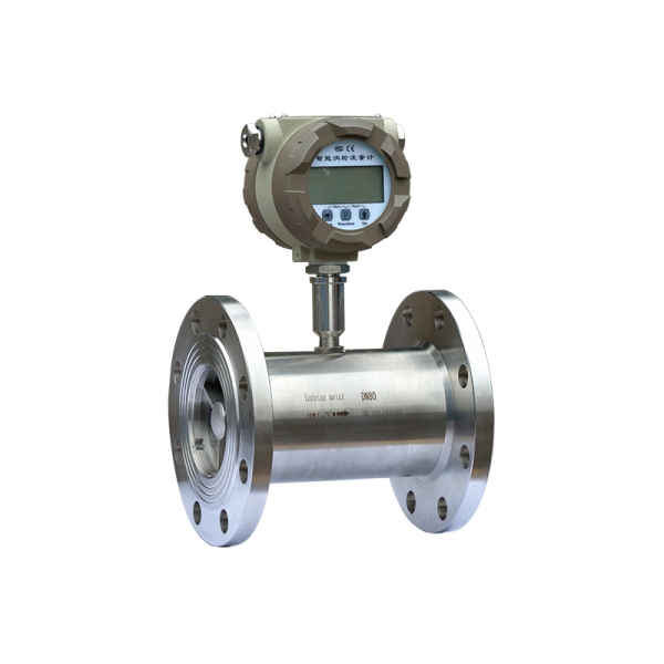 One, the choice of installation location The sensor should be installed in a place where maintenance is convenient, the piping is free of vibration, and there is no strong electromagnetic interference and heat radiation. The configuration of each part in the figure differs depending on the condition of the object to be measured, and it is not necessarily required. Because TUF is very sensitive to the strain and swirling flow distribution in the tube, the inlet sensor needs to fully develop the flow of the tube. Therefore, it is necessary to equip the necessary straight pipe section or flow regulator according to the type of the upstream resistance body of the sensor. When the situation is not clear, generally the length of the upstream straight pipe section is that if the installation space cannot meet the above requirements, install a flow regulator between the resistor and the sensor. When the sensor is installed outdoors, direct radiation must be avoided. 2. Precautions for installation location For the sensor installed horizontally on the turbine flowmeter, the pipe must have no visible inclination (within 5)), the vertical deviation of the sensor pipe installed vertically is less than 5, and the direction of the fluid must be from bottom to top. Where the flow cannot be stopped, please install a bypass valve and a shut-off valve. When the fluid contains impurities, a filter should be installed on the upstream side; if it contains gas, please install a getter on the upstream side. The outlet and exhaust of the filter and air entrainer must lead to a safe place. The flow regulating valve is installed downstream of the sensor, and the upstream shut-off valve should be fully opened during measurement to avoid vibration and leakage. If there is a possibility of backflow, please install a check valve to prevent backflow of the fluid. The sensor is concentric with the pipe. Do not protrude the gasket onto the pipe. In order to prevent the gas accumulated in the piping, such as the gas mixed with air when the flow is stopped, staying on the sensor, making it difficult to discharge and affecting the measurement, please do not make the height of the piping further level with the sensor. Please firmly support the piping before and after the sensor to avoid vibration. For fluids that are prone to condensate, take heat preservation measures for the sensor and the piping before and after it. Transmission cables usually use 2-core or 3-core shielded signal cables. The shielded signal cable is grounded at one end of the display (flow totalizer or flow calculation controller), and the transmission path should not be parallel to the power cord. In addition, do not lay in areas where power and power lines are concentrated. 3. Precautions for low temperature and high temperature fluids The low-temperature fluid pipeline discharges the water in the pipeline before circulation, runs at a small flow rate of 15 minutes during circulation, and then gradually rises to the normal flow rate. When stopping the flow, please proceed slowly so that the piping temperature and the ambient temperature gradually approach. High temperature fluid operation is similar to this. Four, extend other matters needing attention 1. The on-off valve should be relaxed as much as possible. When the switch is automatically controlled, use the “two-stage open and two-stage close” method to prevent the fluid from suddenly hitting the impeller and causing water hammer to damage the impeller.
Post time: 21-09-21