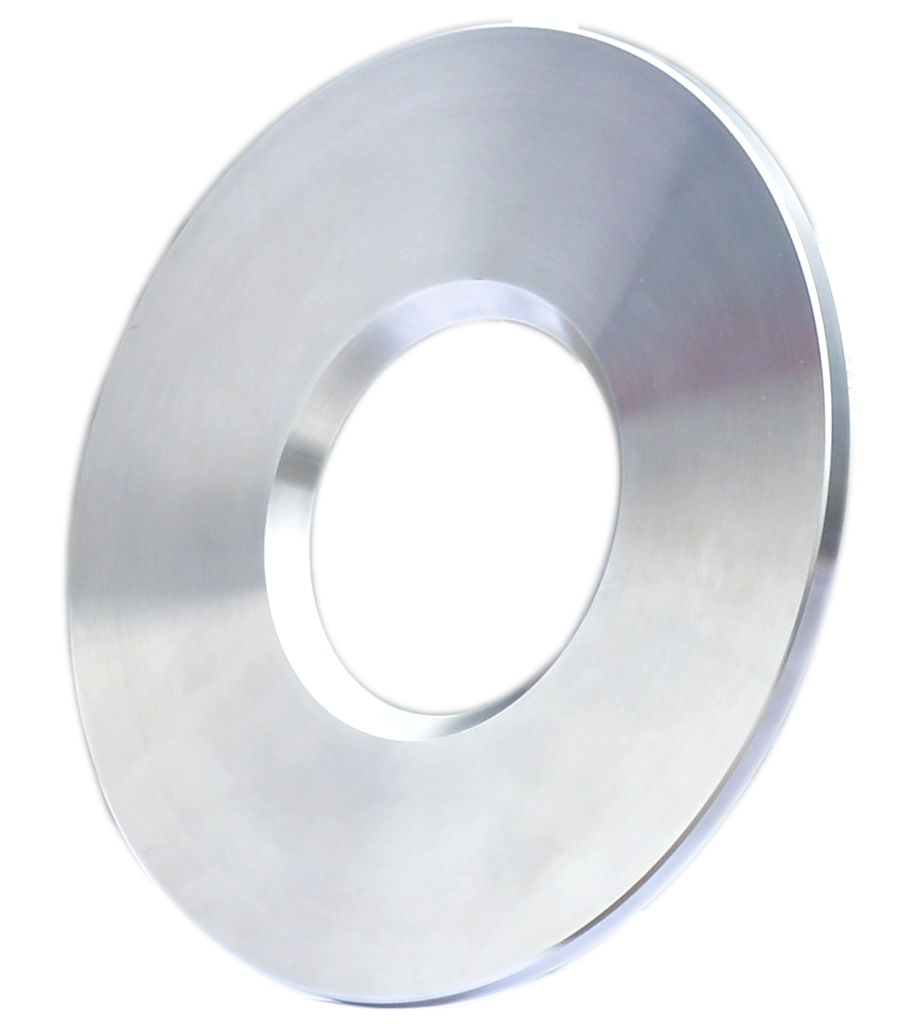
Nozzle flowmeter is a differential pressure generating device for measuring flow. It can measure the flow of various fluids in the pipeline with various differential pressure gauges or differential pressure transmitters. The standard nozzle throttling device is used in conjunction with a differential pressure transmitter to measure the flow of liquid, steam, and gas. It is widely used in petroleum, chemical, metallurgical, electric power, light industry and other sectors.Installation of nozzle flowmeter:Integral installation is composed of a nozzle flowmeter with an intelligent display (multi-variable transmitter) and a nozzle device. It comes with high-quality differential pressure sensor, pressure sensor, thermal resistance temperature sensor. The AW2003-type intelligent display instrument (multivariate transmitter) not only automatically adapts to the range of the differential pressure sensor, but also various compensation coefficients such as: outflow coefficient C, stream expansion coefficient ε, etc. are calculated online, which truly realizes the expansion At the same time of measuring range, the accuracy of measurement is ensured. The large-screen LCD is used to display the cumulative flow, instantaneous flow, instantaneous pressure, and instantaneous temperature values on the same screen without manual switching. 4-20mA two-wire instantaneous flow output. It is divided into two categories: intrinsically safe explosion-proof products and ordinary products. Split installation is composed of independent nozzle device, differential pressure, pressure, temperature transmitter, flow calculator, stop valve and other parts. The connection combination between the various parts is completed by the user himself.The nozzle flow transmitter is composed of a nozzle flow sensor and a differential pressure transmitter. It outputs a 4-20mA electrical signal representing the size of the differential pressure signal. The flow calculation and temperature and pressure compensation are separately configured by the user. There are two structures, split installation and integrated installation. The integrated installation means that the differential pressure transmitter and the nozzle have been connected into one when the product leaves the factory. After the user purchases the integrated nozzle, there is no need to connect the pressure pipe when using it. But it must be equipped with corresponding flow calculator, pressure transmitter and temperature transmitter. The split nozzle flow transmitter consists of an independent nozzle flow sensor and a differential pressure transmitter. The pressure pipe connection between the nozzle flow sensor and the differential pressure transmitter is completed by the user. nozzle flow sensor characteristics: only provide the forming part of the differential pressure signal (nozzle part), does not provide the differential pressure transmitter and flow calculation display part, the output signal is the pressure difference formed by the fluid before and after the throttle. It is up to the user to make other configurations.Features of nozzle flowmeter:Compared with the orifice flowmeter, the nozzle flowmeter has a smaller pressure loss, so it saves energy, is more sturdy and durable, suitable for high temperature and high pressure fluid, and is widely used in steam flow measurement in the power, chemical and other industries. Nozzle flow meters include standard nozzles (ISA1932 nozzles) and long-necked nozzles. Its design and manufacturing are in compliance with the international standard ISO5167 or the national standard GB/T2624.(1) Standard nozzleThe standard nozzle is composed of an entrance plane part A perpendicular to the axis, an entrance constriction formed by arc-shaped curved surfaces B and C, a cylindrical throat E, and a protective groove F required to prevent edge damage. The pressure is taken upstream. The pressure taking port adopts a corner joint to take pressure, and the downstream pressure taking port can be set according to the corner joint to take pressure, or it can be set far downstream.Total nozzle length:When 0.30≤β≤2/3, the nozzle length=0.6041d ? When 2/3≤β≤0.80, the nozzle length={0.4041+(0.75/β-0.25/ β2-0. 5225)0.5}d ? The upstream surface of the ISA1932 nozzle (Figure 4. Nozzle composed of grooves. ISA1932 nozzle has only one way of tapping pressure.Applicable medium; especially suitable for high temperature and high pressure steam and water, and can also be used for various gases and liquids. Nominal diameter: DN50—500mm (DN>500 can also be designed and produced). Working pressure: ≦42MPa. Working temperature: -50℃—650℃. Pressure taking method: angle connection (separate ring chamber, flange ring chamber as a whole or direct drilling) to take pressure. Nozzle installation method: flange (direct drilling and pressure part), fastener clamping type, flange, ring chamber, fastener clamping type, clamping part (also pressure part) welding type. Executive standard: IS05167; GB/T2624. Accuracy: Meet the standard: ±1.0%. Material: Flange or clamping parts: Carbon steel, alloy steel, stainless steel, etc. can be selected according to the temperature of the medium. Nozzle: stainless steel 304, 316, etc. (2) Long-diameter nozzle The upstream surface of the long-diameter nozzle is a nozzle composed of a plane perpendicular to the axis, a constricted section with a 1/4 ellipse profile, a cylindrical throat, and possible grooves or bevels. There is only one pressure method for long diameter nozzles: D-D/2. Applicable medium; especially suitable for high temperature and high pressure steam and water, and can also be used for various gases and liquids. Nominal diameter: DN50—630mm. Working pressure: ≦42MPa. Working temperature: -50℃-650℃. ? Pressure taking method: Diameter (D-D/2) pressure taking. Nozzle installation method: equipped with and welded the upper and downstream pipe sections, and then set the pressure hole according to the diameter (D-D/2). Executive standard: IS05167; GB/T2624. ? Accuracy: in line with the standard: ± 2.0%. Material: Carbon steel, alloy steel, stainless steel, etc. can be selected for the upstream and downstream pipe sections according to the temperature of the medium. nozzle: stainless steel 304;, 316, etc.
Post time: 21-09-21
