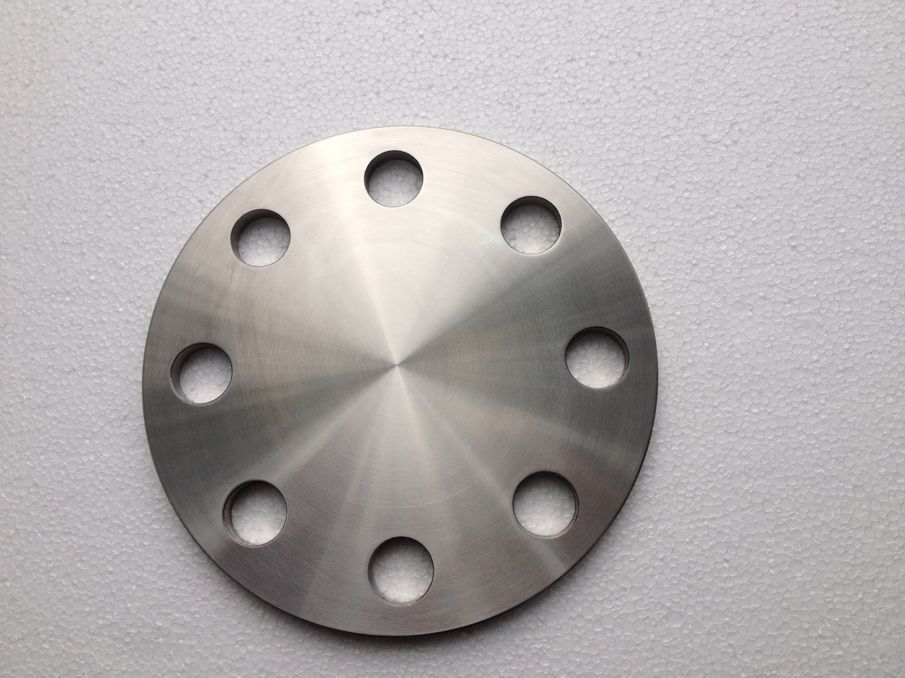
The differential pressure flowmeter is an instrument that measures the flow according to the differential pressure generated by the flow detection element installed in the pipeline, the known fluid conditions and the geometric dimensions of the detection element and the pipeline. The differential pressure flowmeter is composed of a primary device (detection part) and a secondary device (differential pressure conversion and flow display instrument). Differential pressure flowmeters are usually classified according to the type of detection parts, such as orifice flowmeters, venturi tube flowmeters, and averaging velocity tube flowmeters.Differential pressure flowmeter installation requirements:1. The flowmeter should be concentric with the pipeline.2. The gasket should be concentric with the pipe and cannot protrude from the pipe.3. The maximum height of the two pressure guiding tubes must be the same.4. There must be a root valve (stop valve) to take pressure.5. Antifreeze.Installation details of differential pressure flowmeter:First of all, it depends on whether you are measuring gas, liquid or steam. The gas pressure port is preferably on the upper part of the pipe; the liquid pressure port is on the side but not directly below, the deposition particles will block the pressure port; for steam, the pressure port is on the side of the pipe;2. Don’t make a mistake about the direction of the orifice, the “+” is the positive direction, the “-” is the negative direction, and the “+” is the direction facing the fluid.3. The pressure guiding tubes from the positive and negative pressure taps must be kept parallel under any circumstances;4. The orifice plate is generally used with a differential pressure transmitter. When connecting the pressure guiding tube and the differential pressure transmitter, pay attention to the positive and negative pressure not to be installed reversely, “H” is positive, and “L” is negative;5. It is recommended that the differential pressure device be placed above the pipe for gas measurement, and placed at the bottom of the pipe for liquid. If a condensing tank is provided for steam measurement, the condensing tank should be kept at the same level.6. I forgot the requirements for straight pipe sections. The orifice plate should have a calculation book. The length of the front and rear straight pipe sections required for the installation of the orifice plate is calculated above. It is best to follow that. If you can’t find it, you can install it according to the first 20D and the 10D (D Refers to the caliber of the orifice).
Post time: 21-09-21
