The installation of the integrated orifice flowmeter should comply with the installation requirements of the flow source components in the Automation Instrumentation Engineering Construction and Acceptance Specification (GB50093-2002), namely:When measuring gas flow, the pressure port is in the upper half of the pipeline;When measuring the liquid flow, the lower half of the pipeline and the horizontal centerline of the pipeline form an angle of 0~45°;When measuring the steam flow, the upper half of the pipeline and the horizontal centerline of the pipeline form an angle of 0~45°;Precautions for installation of orifice flowmeter:1. The gas pressure port should be on the upper part of the pipe; the liquid pressure port should be below the side but not directly below, as deposited particles will block the pressure port; for steam, the pressure port should be on the side of the pipe;2. Don’t make a mistake about the direction of the orifice. The one marked “+” is positive, “-” is negative, and “+” is the direction facing the fluid.3. The pressure guiding tubes from the positive and negative pressure taps must be kept parallel under any circumstances;4. The orifice plate is generally used with a differential pressure transmitter. When connecting the pressure guiding tube and the differential pressure transmitter, pay attention to the positive and negative pressure not to be reversed, “H” is positive, “L” is negative;5. It is recommended that the differential pressure device be placed above the pipe for gas measurement, and at the bottom of the pipe for liquid. If a condenser is provided for steam measurement, the condenser should be kept at the same level.6. Straight pipe section is required, calculate the length of the front and rear straight pipe sections required when installing the orifice plate according to the calculation book, usually the first 20D and the rear 10D to install (D refers to the diameter of the orifice) throttling device V-cone flowmeter and orifice flowmeter Performance comparison: V-cone flowmeter (also known as inner cone, V-cone, V-cone flowmeter) is a new generation of differential pressure flowmeter measuring instrument, which consists of a special throttling device conical tube and a general differential pressure transmission The supporting structure of the instrument and the secondary instrument. The tapered tube is a technical product, which has made great technical improvements to the old differential pressure device. It consists of a circular measuring tube and a special core that is placed in the measuring tube and coaxial with the measuring tube. Between the core and the inner cylindrical surface of the measuring tube, a different-diameter annular flow crack is formed to throttle the flowing fluid. The throttle history is similar to that of the annular orifice and the classic venturi tube. The special structure of the tapered tube effectively eliminates the performance defects of the orifice plates and nozzles currently in use, so that the sharp-edge abrasion and fouling of the orifice plates and other throttling parts will not persist in the course of use, and the joints can be aligned. The fluid velocity dispersion gradient in the flow tube and the presumably permanent various non-axisymmetric velocity dispersion perform additional effective flow resolution (rectification), which can achieve high-accuracy and high-level flow measurement. Conical tube flowmeter can be used to measure various liquids, gases and steam. It is a dream replacement product for dilapidated throttling instruments such as size orifice plates. It provides an effective, Reliable measurement of the wrist.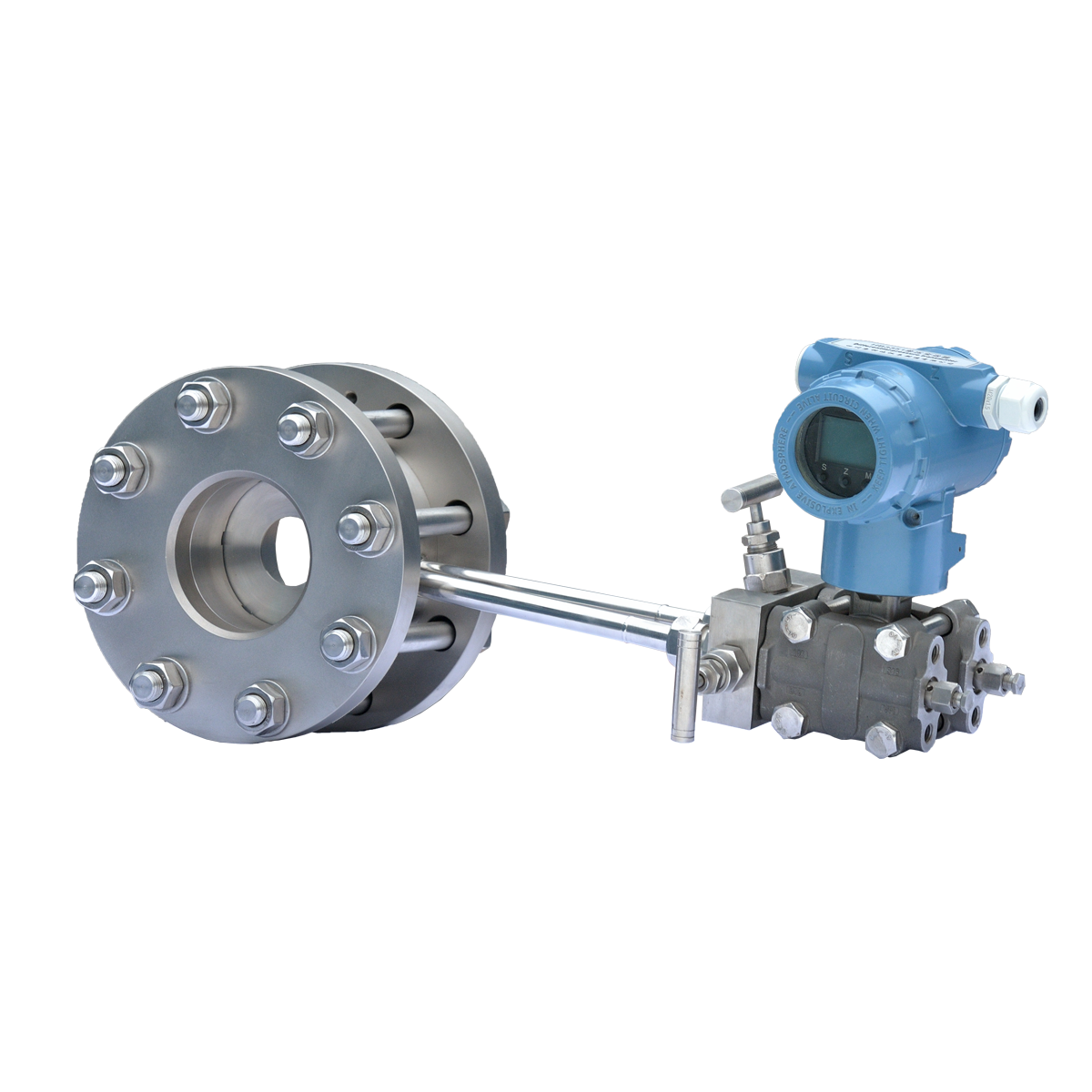
Post time: 21-09-21