Turbine flowmeter is the most common measuring instrument, and it is the earliest legal flowmeter in Europe. Most users in my country also like to use turbine flowmeter. There are gas turbine flowmeter and liquid turbine flowmeter. The common classification methods are as follows.Turbine flowmeter1. Classification by signal detection method1. Inductive. Permanent magnetic material is embedded in the sensor impeller. When the impeller and the permanent magnetic material rotate, the magnetic field alternately approaches and moves away from the detection coil outside the sensor housing. The induced electromotive force of the coil changes with it, and the periodically changing frequency signal is amplified and output.2. Variable reluctance type. The impeller blade or hub is made of magnetic material, and the detection coil outside the sensor shell is equipped with water magnetic material. When the impeller rotates, the magnetic circuit formed by the permanent magnetic material in the ring, because the magnetic blades alternately approach or move away, the magnetic flux changes periodically, and the equivalent impedance of the coil also changes, producing continuous pulses in the amplifier circuit. Wave.3. Reed pipe (dry reed pipe) type. The permanent magnetic material embedded in the impeller (or other rotating elements synchronized with it) periodically opens and closes the reed of the outer flute of the sensor housing for electric shock. This switching action causes the constant current (or constant voltage) source to generate electrical pulse signals.4. Photoelectric. The impeller blades or elements driven by the impeller periodically interrupt the light beam as the impeller rotates, and the generated light pulse signal is converted into an electric pulse signal. In recent years, optical fiber transmission methods have appeared, which effectively improves the anti-interference performance. 2. Classification by flow direction1. One-way type. Only allow fluid to flow into the sensor from one direction, and install a check valve where there is a possibility of backflow. 2. Two-way type. Allows fluid to flow into the sensor from both positive and negative directions. There are two signal detectors, and the flow display instrument can identify the phase of the signal. The cumulative amount uses “plus” or “minus” to deal with the total amount of flow in the “positive” or “reverse” directions. For example, turbine flowmeters for submarines. Three, according to the sensor and pipeline connection method classification 1. Flange connection type. The sensor is connected to the pipeline in the form of a flange. The flange of the finalized product is in accordance with the national standard. The pressure is limited to 6.3Mpa or less. 2. Threaded connection type. The sensor is connected to the pipeline in a threaded manner. There are two types of threads: sealed pipe threads and non-sealed pipe threads, which can withstand high pressure, but are not suitable for larger diameters. 3. Clip-on type. The sensor itself cannot be flanged, and the two sealed end faces of the sensor are clamped by the flange on the pipe. The installation is convenient, and it is not suitable for higher pressure and larger diameter.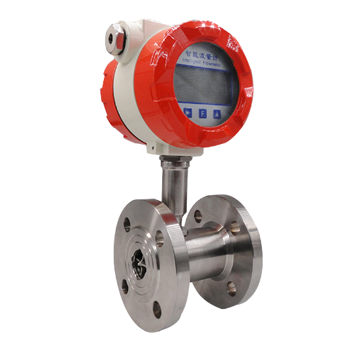
Post time: 21-09-21