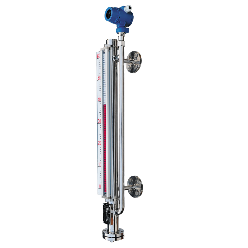
The remote magnetic flap level gauge is a 4-20mA current signal conversion remote transmission device added to the on-site display, as shown in the following figure: The working principle of the remote transmission device of the remote magnetic flap level gauge LB The liquid level transmitter is composed of a liquid level sensor and a conversion module. The liquid level sensor is composed of a set of dry reeds and resistance chains. The electrical connection of reed switch J and resistor R is shown in Figure 1. Reed switches and resistors are set every 10mm and installed in a stainless steel tube at equal distances. The resistance of all resistors is the same, that is: R1 =R2 =R3 =Rn. The number of resistances is determined by the liquid level measurement range (that is, the length of the ruler). For example, when the measurement range is 1200mm, the number of R resistors n is n =1200 10 =120 (pieces). The liquid level sensor and the magnetic flap level gauge are installed in parallel on one side of the float, and they are both in the magnetic lotus coupling system of the magnetic float. When the magnetic float moves up and down with the liquid level, the reed switch of the corresponding height is attracted by the magnetic field, so that the resistance value of the resistance chain, that is, the resistance value Rab shown at points a and b in Figure 1 changes. For example, when the liquid level is at the lowest position, J0 pulls in, and all resistors are short-circuited by J0, Rab is 0; when the liquid level is at the highest position, Jn pulls, Rab is the sum of n resistors in series. That is: when the liquid level is 0%, Rab =0, when the liquid level is 100%, Rab is the maximum. The conversion module is actually a simple circuit for measuring the resistance value, which is composed of a Ψ/V (resistance/voltage) conversion circuit, a V/I (voltage/current) conversion circuit, and a zero position and range adjustment circuit. The block diagram is shown in Figure 2. The resistance signal corresponding to the height of the liquid level from the liquid level sensor enters the terminals a and b shown in Figure 2, and finally outputs a 4-20mA DC standard signal after processing. So which rules need to be followed during the use of the remote magnetic flap level gauge
1. Do not allow any magnetic material to approach the remote magnetic flap level gauge and its surroundings, and no iron wire can be used to fix it, otherwise it will easily cause adverse effects on the normal working track of the remote magnetic flap level gauge;
2. When the user uses the heat tracing pipeline by himself, the material that needs to be selected is a non-magnetic material, such as a copper tube, etc., and the later heating temperature is actually determined according to the specific medium; 3. Remote magnetic flap fluid Installation of the position gauge: When installing, it must be ensured that it is in a vertical state. A ball valve must be installed between the remote magnetic flap level gauge and the container lead pipe to facilitate later cleaning and maintenance;
Fourth, the medium must not contain solid impurities or magnetic substances to prevent the impact of the float;
5. When officially starting to use, it is required to correct the magnetic steel of the remote magnetic flap level gauge first, and adjust the small ball below zero to red, and other small balls to white; 六, When debugging, it is required to open the upper lead valve, and then open the lower valve at a slow speed, so that the medium can penetrate into the main pipe in a stable state, and the medium needs to be prevented during its operation. The rapid speed impacts the float, which causes violent turbulence in the float, which affects the accuracy of the data read by the remote magnetic flap level gauge.
7. After installation, be sure to reconfirm that the 4mA scale line on the remote transmission device corresponds to the zero scale of the level gauge panel, otherwise the actual liquid level and the remote transmission level display will not correspond to each other during operation.
8. The wiring of the remote transmission device must use shielded cables of good quality or brand to prevent the quality of the shielded wire or the unshielded wire from causing interference of the remote transmission liquid level and causing measurement inaccuracy.
Post time: 26-11-21