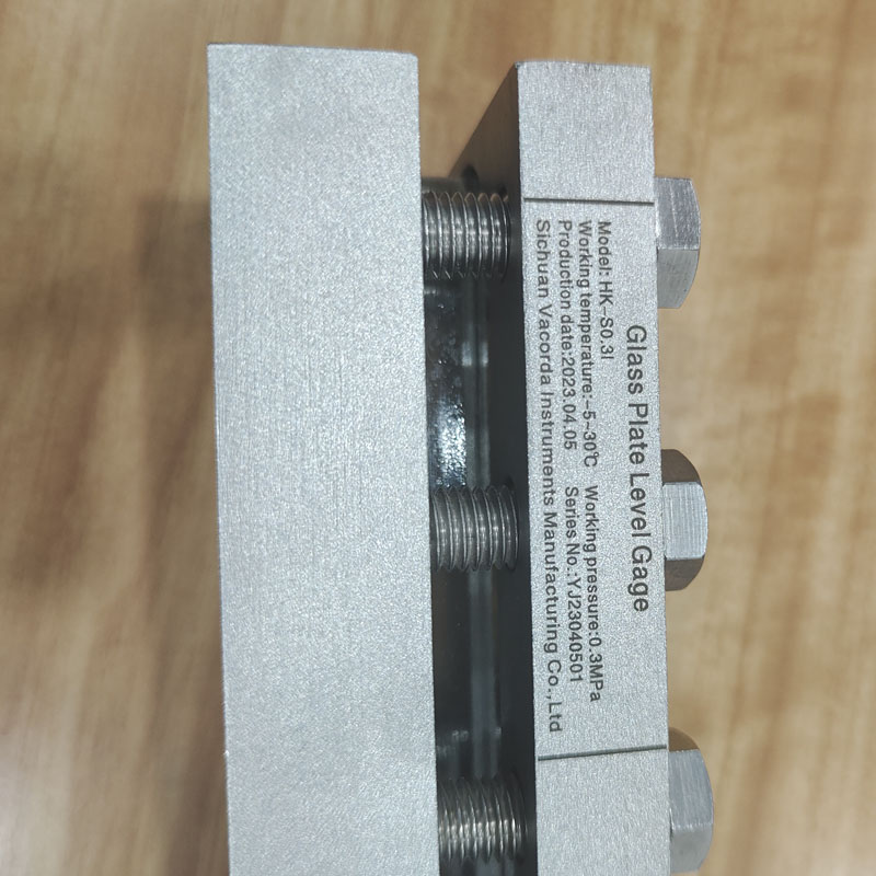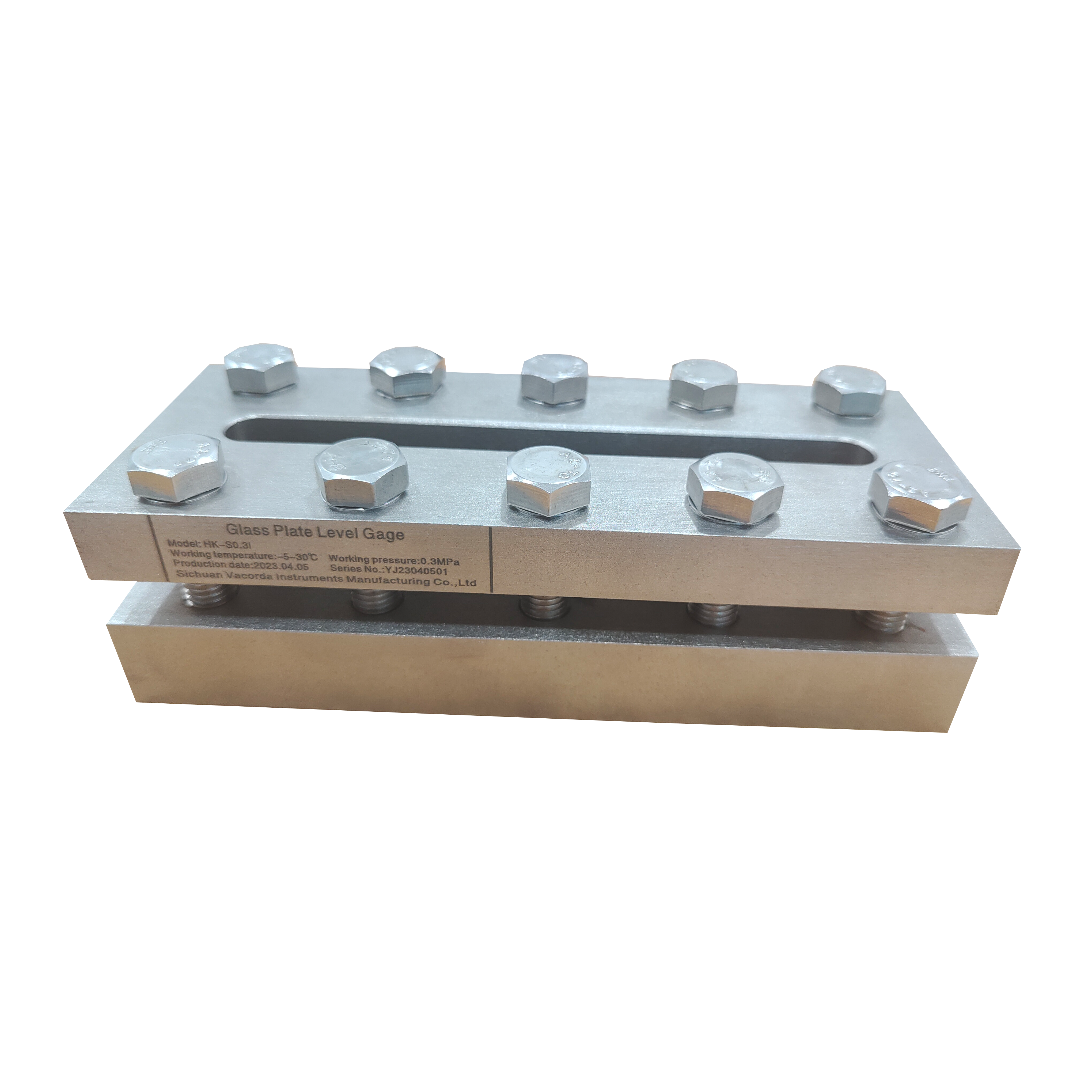


High Temperature Borosilicate Oil level Indicator Sight Glass Level Gauge
Product Description
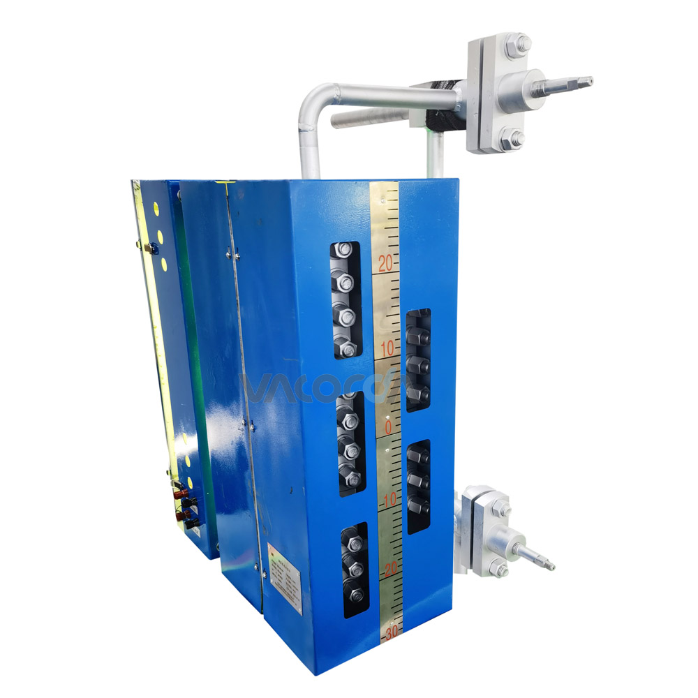
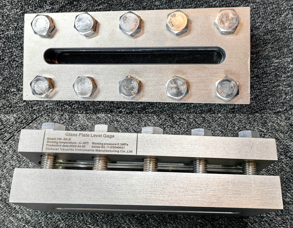
The glass plate liquid level gauge is divided into three types: transparent type, reflx and sight glass. The liquid level gauge is mainly composed of a liquid level gauge body, an upper valve (a steam valve), a lower valve (a liquid valve), a sewage plug(sewage valve), and an insurance steel ball. When the glass plate is damaged by splitting or the like, the safety steel ball automatically blocks the gas and liquid side valves to prevent or reduce the outflow of the medium, and is convenient for manually cutting the root valve of the liquid level gauge for processing. The series is sturdy, reliable and easy to install. It is an ideal instrument for liquid level observation in various medium and low pressure vessels. The liquid level gauge is connected to the upper and lower flanges of the liquid level
gauge and the upper and lower flanges of the container to form a communicating device, so that the liquid level can be directly observed. This product implementation standard: HG 21588-21592-95
Product Features
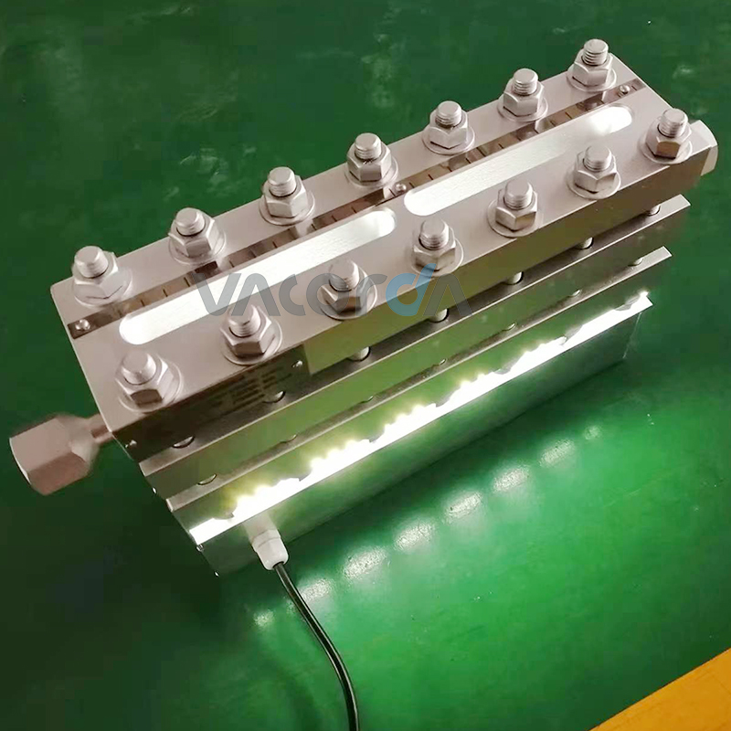
1. Directly observe the liquid level position;
2. It has a quick shut-off device for vapor and liquid leakage;
3. Reasonable structure, simple installation and maintenance;
4. Low maintenance costs;
Main Technical Parameters
1. Working pressure: ≤ 25.0MPa
2. Working temperature: ≤250°C (specially up to 450°C)
3. Center distance (mm): 550, 850, 1150, 1450, 1750 ± 1 ~ 5mm (the center distance is not in the above range of negotiated orders)
4. Mounting flange sealing surface vertical plane error: ≤ 1mm
5. Wetted material: 304, 316L, carbon steel
6. Connection flange standard: HG20592-2009 (user can specify)
Transportation and Installation
1. The instrument should be handled with care during transportation, handling, unpacking and installation. Do not hit, knock or prevent the glass plate from rupturing. This product has been assembled and debugged before leaving the factory, and the pressure test is completed. Users should not loosen the fasteners at random, otherwise the pressure tightness test should be carried out.
2. When installing, the center distance of the upper and lower flanges of the user equipment container, the flange size and the flange orientation must be consistent with the center distance of the instrument, the flange specification and the flange orientation. Otherwise, the installation cannot be performed.
3. In order to ensure the safe operation of the user, the user must install a primary valve on the upper and lower flanges of the container and the upper and lower flanges of the instrument, and at the same time provide guarantee for the maintenance and maintenance of the instrument.
4. When installing, the sealing surface of the connecting flange of the container equipment should be on the same plane and the mounting screw holes are symmetrical. The installation of the instrument shall not have any additional pressure applied to the glass plate to prevent the glass plate from being broken during installation or operation.
5. Check the sealing points after installation and maintenance, and there must be no leakage.
6. The liquid glass meter should not be replaced by organic glass or ordinary glass.