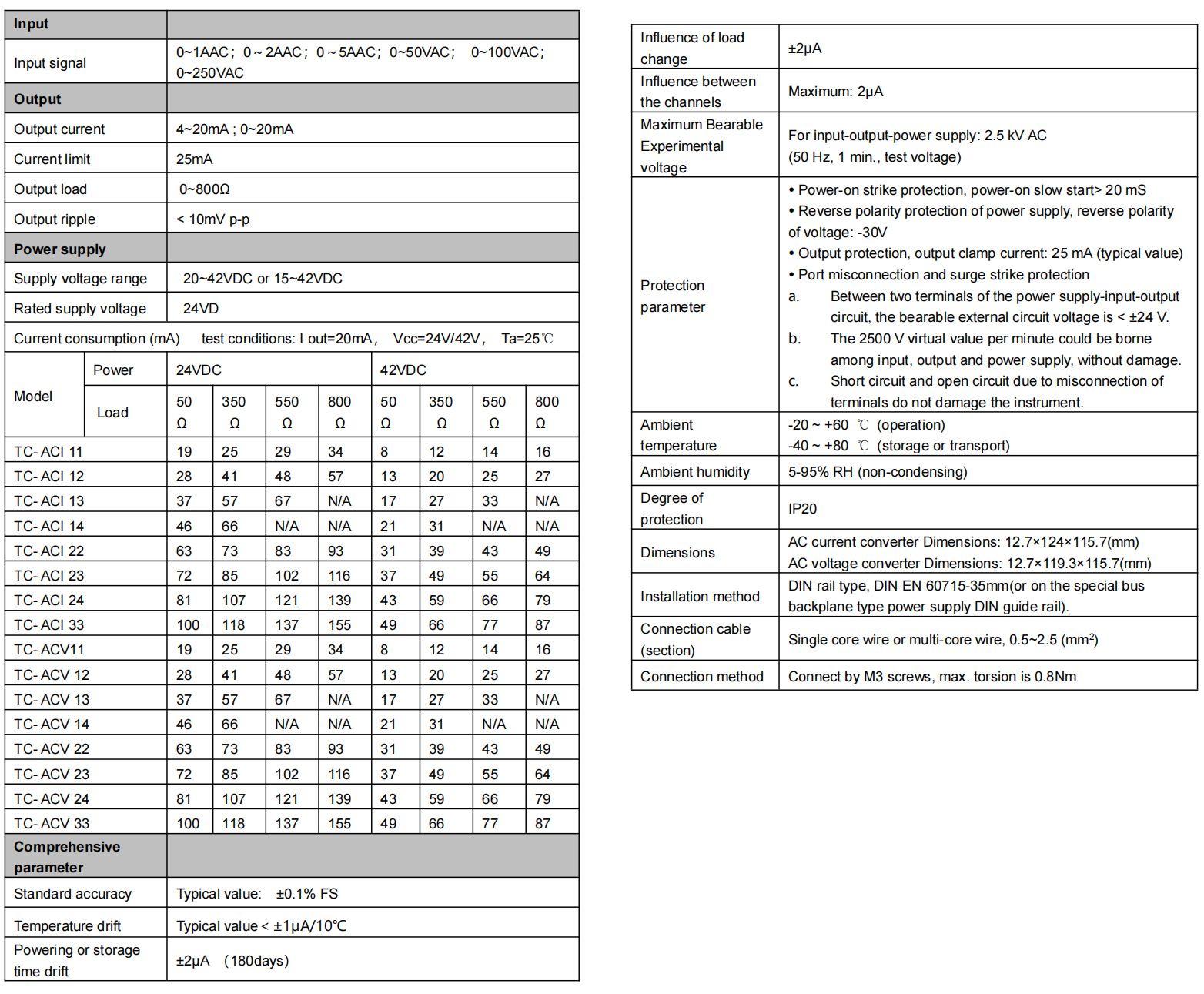
The TC-AC signal isolation converter has the function of converting the AC with a virtual value of 0~5 A and AC voltage with virtual value of 0~250 V into 4~20 mA standard signal (but the two signals cannot be input simultaneously). The conversion accuracy is ±0.05% FS, and there is no dead zone near zero input signal.
An input terminal is not set for the current input signal, which shall be connected to the internal converter through the secondary side of the single loop current transformer. The current transformer turn ratio is 1:1,800, and the actual input signal of converter is 0~2.78 mA. No high heat is generated on the terminal blocks.
The voltage input signal enters into the converter by means of terminal block and the current of input voltage circuit is limited to 0~2.78 mA to make the actual input signal of the converter equal to the actual signal of the current input, which can be achieved by using the same converter without switching over.
Accuracy ±0.05% FS Temperature drift (typical value) <±1μA/10 ℃. -20 ~ +80 ℃ temperature test, typical value < ±10 μA.
Output signal: 4~20 mA or 0~20 mA.
Output self-adaptive load: 0~800 Ω. High limit of the output current is 25 mA. Load change error < ±2 μA/800 Ω; impact of load open circuit on the other output < ±2 μA.
The power supply range can be chosen from within range of 20~42VDC or 15~42VDC.
See the “Technical Data Sheet” in the specifications for current consumption or other functional indices.
There is no power light on the instrument panel. The power supply indicator is replaced by a model printed on the instrument panel. After the power is on, the model on the panel becomes illuminated by means of the LED backlight.
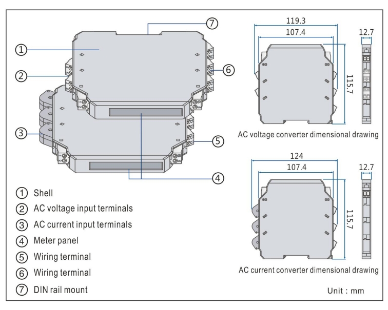
Clamping type structure, 35 mm DIN standard guide rail clamping type installation is used. Screw terminal, the wire is connected and fastened by M3 screws.
■ Model, model selection and ordering
Model selection example
Example 1. TC-ACI11-AA-V1 ……1-input & 1-output, AC signal converter(0~1AAC input,4~20mA output; terminal power supply 20~42VDC)
Example 2. TC-ACV11-CA-V2…...1-input & 1-output,AC signal converter(0~250VAC input,4~20mA output; guide rail power supply 20~42VDC)
Note: if you select products with guide rail power supply, please order the special power supply DIN guide rail as well.
Optional accessories: Special power supply DIN guide rail (1 m/pc) PSDR-9000
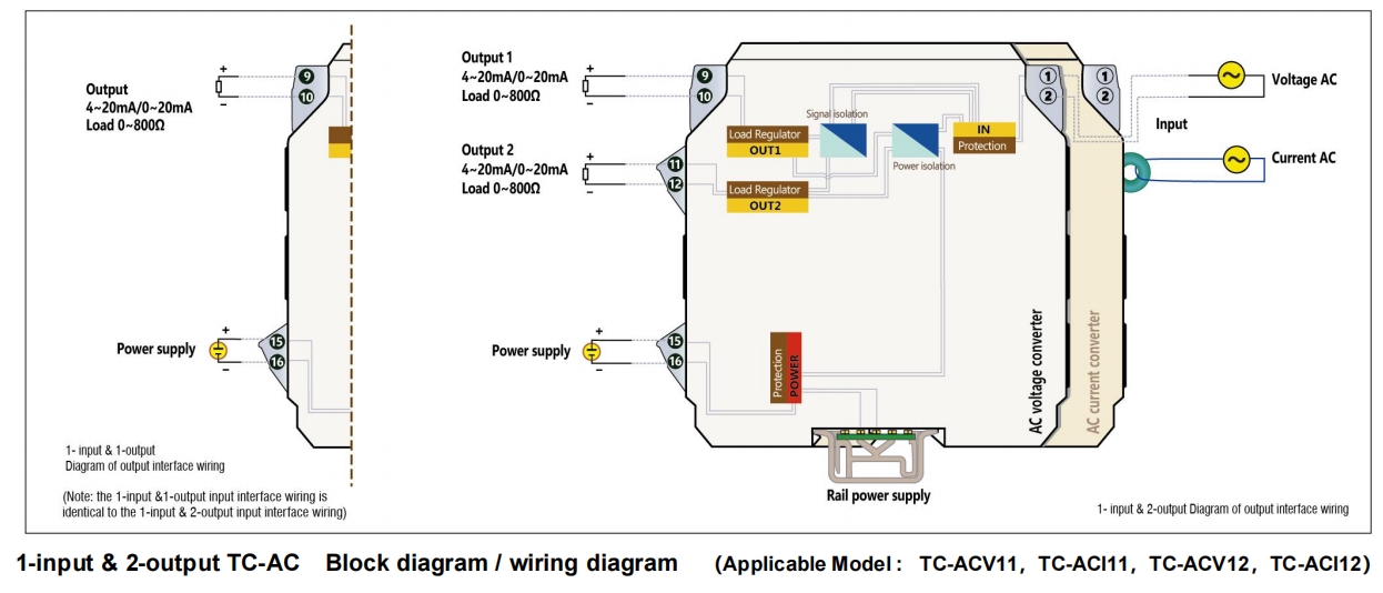
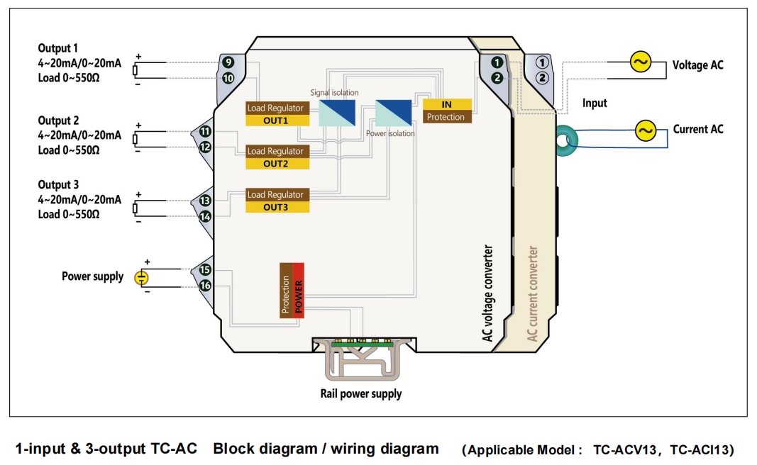
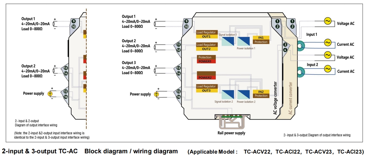
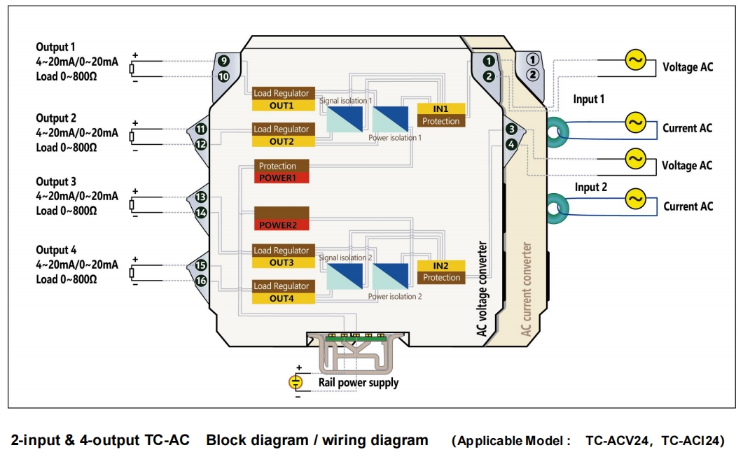
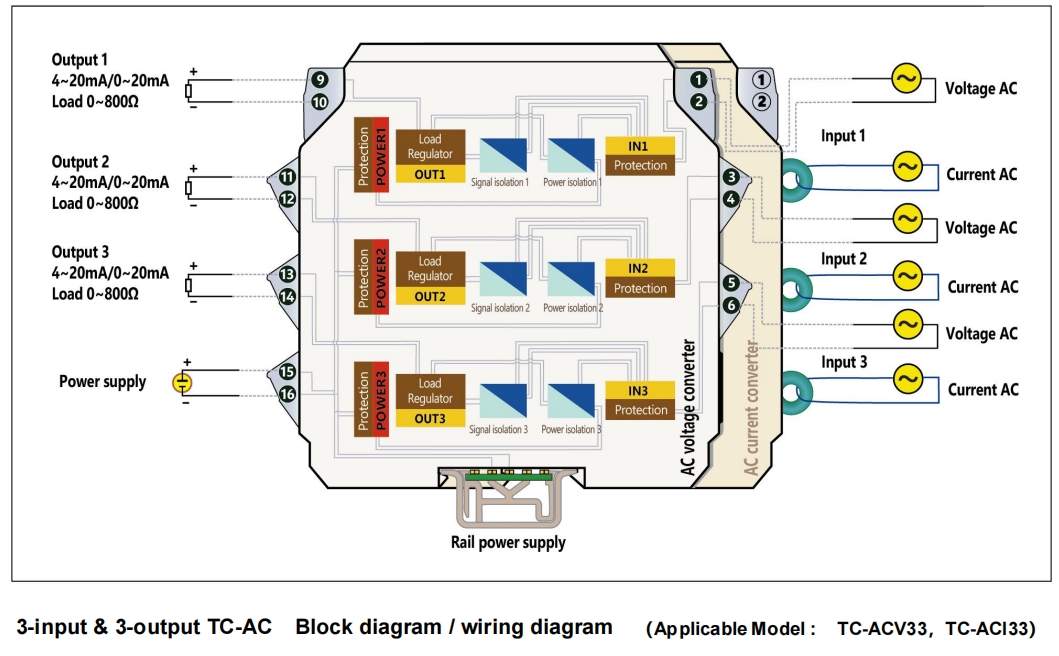
■ Block diagram/wiring diagram