TC-ZT is used to input the thermal resistance or thermocouple signal, which following
isolation is converted into the standard current signal and then transmitted to the control
systems or other instruments.
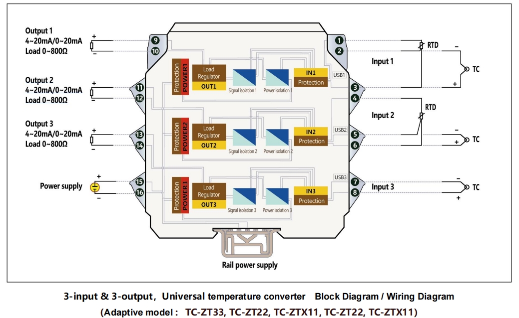
Switches thermocouple and thermal resistance input signals according to various wiring
modes. When the number of input signals reaches the maximum amount, the configuration
becomes three-circuit thermocouple or two-circuit thermal resistance plus one
thermocouple.
The input type (graduation) or range configuration can be set. Configuration parameters
only include three items, i.e. signals (or graduation), null point and full scale, which can be
conducted in the state of no power. The accuracy after normal use will be greater than
0.03% FS. Input is open circuit or short circuit, the output is above the high limit or below
the low limit, the default value of the configuration is output greater than 22 mA. The
configuration can also be reset.
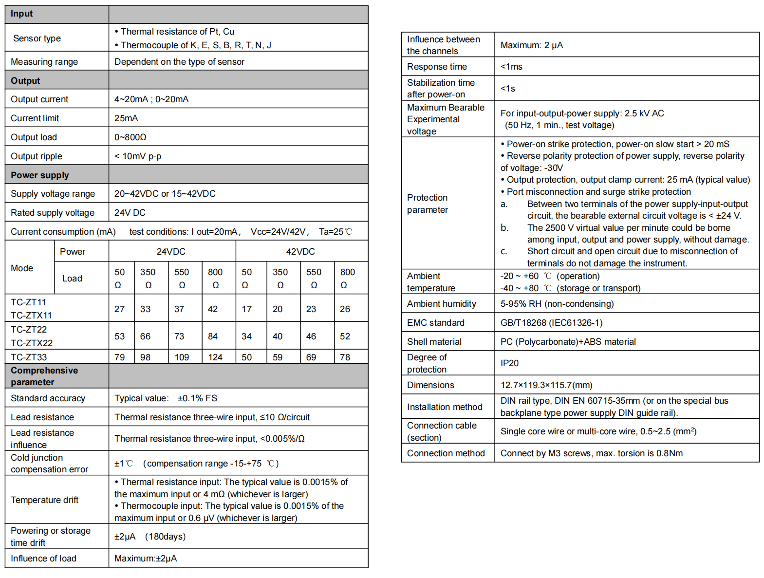
Thermal resistance input range: 10 Ω~400 Ω; minimum resolution: ±2 mΩ; stability:
±3 mΩ. When the compensating lead error of three-wire input is not less than 50 ℃ range
(Pt100), the additive error is not more than ±0.02 ℃.
Thermocouple input voltage range: 4-80 mV; minimum resolution: ±1 μV; stability: ±2 μV.
The additive error of cold junction compensation is not more than ±1 ℃.
Output signal: 4~20 mA or 0~20 mA.
The output self-adaptive load is 0~800 Ω.
The power supply range can be chosen from within range of 20~42VDC or 15~42VDC.
See the “Technical Data Sheet” in the specifications for current consumption or other
functional indices.。
There are LCD and LED backlight options for the instrument panel of the thermocouple
or thermal resistance input intrinsically safe isolator. The LCD can display the input value,
output value, or the position number required by the user. In case of no LCD, the LED
backlight design shall be used for the instrument panel. There is no power light on the
instrument panel. The power supply indicator is replaced by the model printed on the
instrument panel. After the power is on, the model on the panel becomes illuminated by
means of the LED backlight.
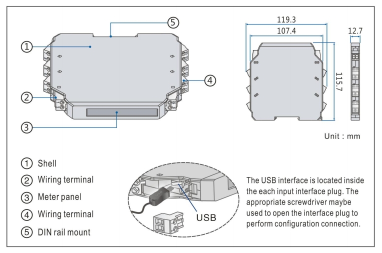
Clamping type structure, a 35 mm DIN standard guide rail clamping type installation is
used. Screw terminal, the wire is connected and fastened by M3 screws.
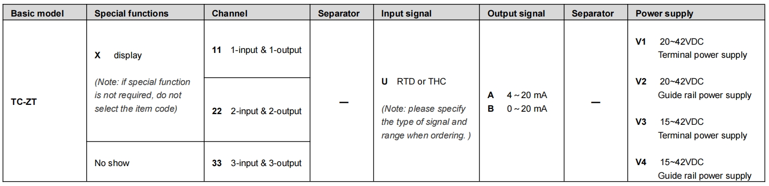
■ Model, model selection and ordering
Model selection example
Example 1. TC-ZTX11-UB-V1 ……1-input & 1-output,Universal temperature converter (Note: please specify the type of signal and range when ordering. )
Example 2. TC-ZT22-UA-V2 …….2-input & 2-output,Universal temperature converter (Note: please specify the type of signal and range when ordering. )
Note: if you select products with guide rail power supply, please order the special power supply DIN guide rail as well.
Optional accessories: Calibrated software CRFW-2000 for winXP and win7 PC
Calibration interface CR-2206 for general products
General product Android calibration interface FAIF-1904
Special power supply DIN guide rail (1 m/pc) PSDR-9000
■ Block diagram/wiring diagram