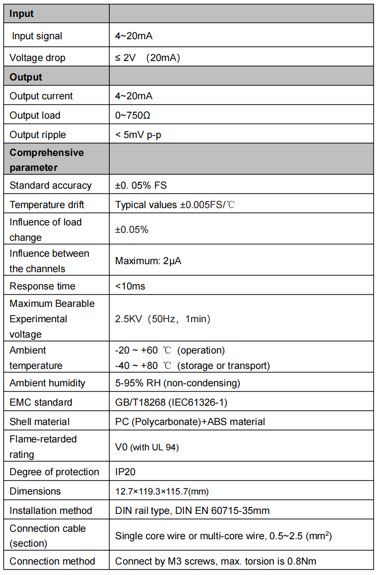
The TC-WY passive isolator is 4~20mA current signal input and 4~20mA current signal output. No additional signal isolator is needed for power supply.
In principle, a passive isolator is a current transformer with modulator and demodulator circuits in the front and rear section. The coefficient of mutual induction is 1:1. No power supply is needed. Energy for isolation transformation comes from the input signal current supply. The external characteristic shows voltage drop of the passive isolator. TC-WY voltage drop < 2 VDC; power consumption: (20 mA×2 V=) 40 mW. This part of the power is mainly consumed on the modulator and demodulator circuit and the transformer wire resistance.
Internal resistance of the current transformer is not the ideal value (infinite). It is easy to measure the specific resistance value. For example: if the load change is 50 Ω and the output current change is 5μA, the internal resistance of the current transformer is (20 mA × 50 Ω/5 μA=) 200 KΩ. It is in parallel with the load. The output signal will thus be shunted. This part of the shunt is shown in the current transformation energy consumption of the current transformer. Though it is fairly small, it can affect the accuracy of the output current. For example: when the load is 600 Ω and the load voltage is (20 mA × 600 Ω=) 12 V; shunt in internal resistance of 200 KΩ is (12 V/200 KΩ=) 60 μA and the output current will be reduced by 60 μA, which is 19.94 mA. The accuracy is only about 0.4% FS.
In order to diminish the above-mentioned error, TC-WY compensates the internal resistance shunt of the current transformer proportionally by detecting load voltage. In this way, the impact of the load change on the output can be reduced by over 20 times. The typical value is <±0.01% FS.
The structure of the passive isolator is simple. It is flexible in use. But attention should be paid during usage:
1 . The load capacity of the input current signal needs to be enhanced. For example, when the voltage drop of the passive isolator is 2 V and the input is 20 mA, the equivalent load is 100 Ω. If the output load is 250 Ω, the load capacity of the input current signal needs to be increased to 350 Ω.
2.Small load operation does not save energy. For example, when PLC input resistance is 50 Ω and the input is 20 mA, the load voltage drop is 1 V. Together with the voltage drop (3V) of the isolator, efficiency is only 33%.
3. When it is used in a heavy-load and high-temperature environment, it is easy for the current transformer to enter a magnetic saturation state. Please make sure that the service ambient temperature is not higher than 60 ℃.
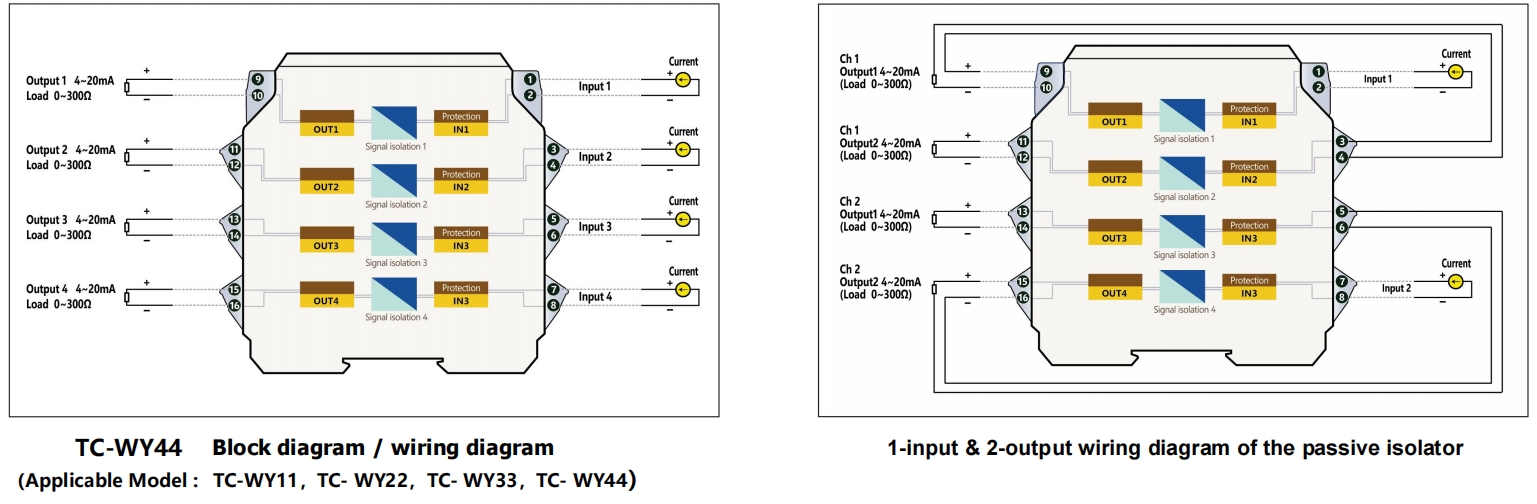
4. As there is no 1-input and 2-output product model, when small loads are used (such as 50 Ω), two channels in series can be employed to achieve 1-input and 2-output (see 1-input and 2-output wiring diagram of the passive isolator). The load capacity of the input current signal needs to be enhanced, however, from 50 Ω to at least 2 (100+50=) 300 Ω.
Accuracy ±0.05% FS, temperature drift: typical value < ±0.005 FS/℃.
When the voltage drop is <2 VDC, output load is 0-750 Ω and load change error is < ±3μA/750 Ω.
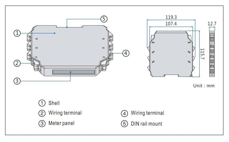
Clamping type structure, with boundary dimension of 12.7×119.3×115.7(mm).Standard 35 mm DIN guide rail clamping type installation is used.
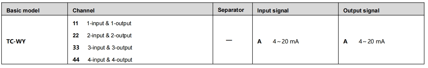
■ Model, model selection and ordering
Model selection example
Example 1. TC-WY11-AA……1-input & 1-output,Passive isolator(4~20mA input,4~20mA output)
Example 2. TC-WY22-AA……2-input & 2-output,Passive isolator(4~20mA input,4~20mA output)
■ Block diagram/wiring diagram