The TC-RTD simulated thermal resistance input isolator is a temperature transmitter
which converts field thermal resistance value into standard current. Analog circuits are fully
adopted. The simulated thermal resistance temperature transmitter has the advantages of
no resolution error and sample period error. It is also of high reliability with no dead halt risk.。
Amongst all the TC serial products, if the simulated temperature transmitter is used to
replace the universal signal isolator with a CPU, this series of products can be used to form
a channel instrument system in full simulation. As relevant products of the control system
are formed by a single CPU, it is hard to achieve functional safety. Therefore, the simulated
temperature transmitter is used as a functional safety alternative solution to achieve and
enhance the reliability and safety of the system.
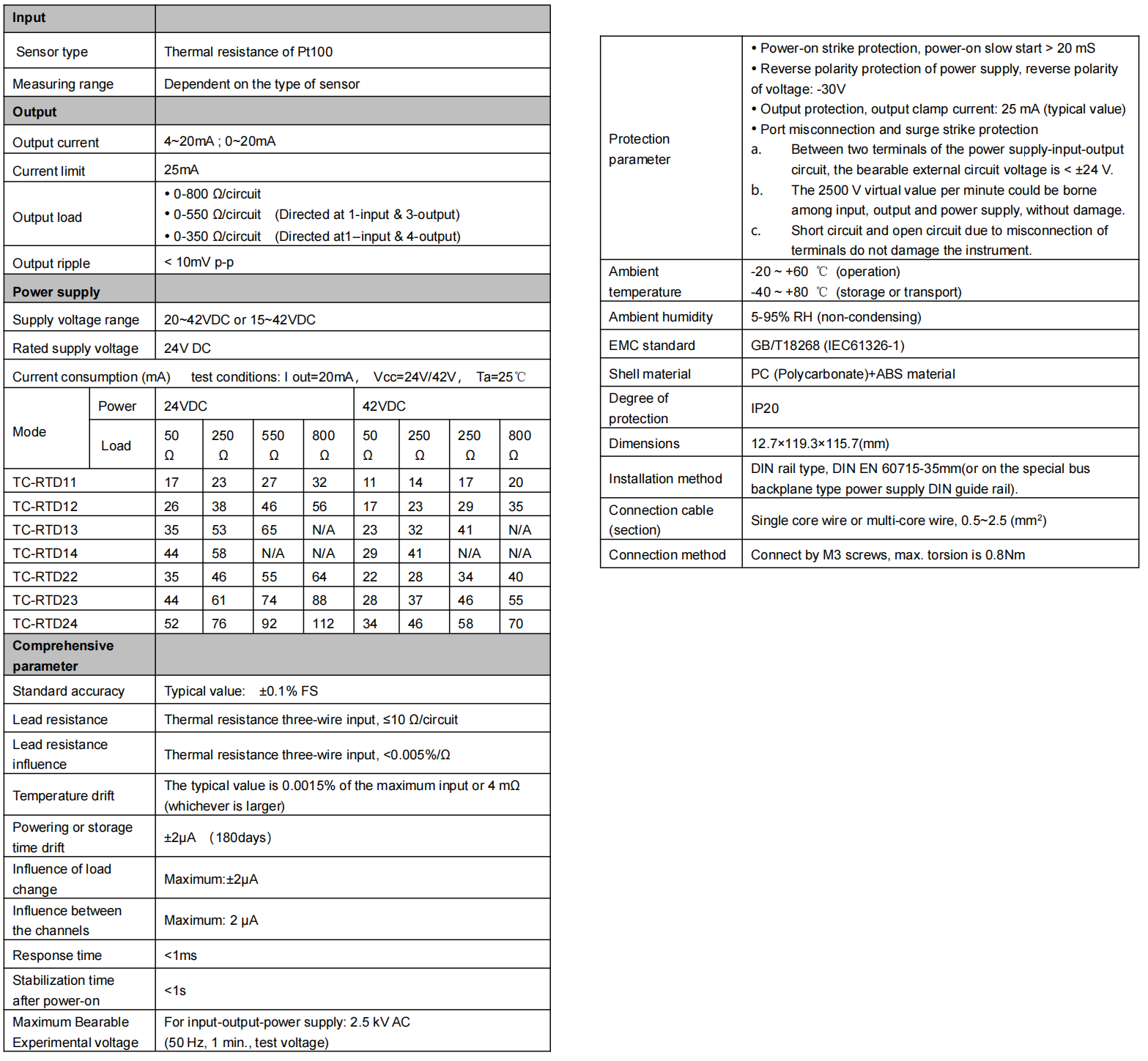
The typical value accuracy is ±0.1% FS. Ex-factory index: ±0.15% FS; the circuit method
of current positive feedback is adopted to achieve linearity correction. Calculation is
completed by Yutong Series R System Control Software 1.1. The calculation accuracy is
±0.03% FS in general.
Thermal resistance graduation and ranges in common use are listed in the column of
“model and model selection & ordering”. It is suggested that the ranges listed for shortening
the supply time and reducing the cost be selected. As for special graduations and ranges
excluded in the scope, the intelligent TC-TP universal signal intrinsically safe isolator can be
used instead. If the single range is large, further discussion is required.
Lead compensation error:<±0.005%/Ω。
Output signals 4~20mA can be extended to 0~20 mA.
Output self-adaptive load is 0~800 Ω. High limit of the output current is 25 mA. Load
change error < ±2 μA/800 Ω. Impact of load open circuit on the other output < ±2 μA.
The power supply range can be chosen from within range of 20~42VDC or 15~42VDC.
See the “Technical Data Sheet” in the specifications for current consumption or other
functional indices.
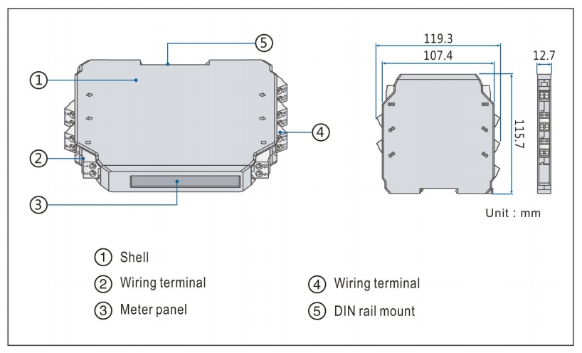
There is no power light on the instrument panel. The power supply indicator is replaced by
a model printed on the instrument panel. After the power is on, the model on the panel
becomes illuminated by means of the LED backlight.
Clamping type structure, a 35 mm DIN standard guide rail clamping type installation is
used. Screw terminal, the wire is connected and fastened by M3 screws.
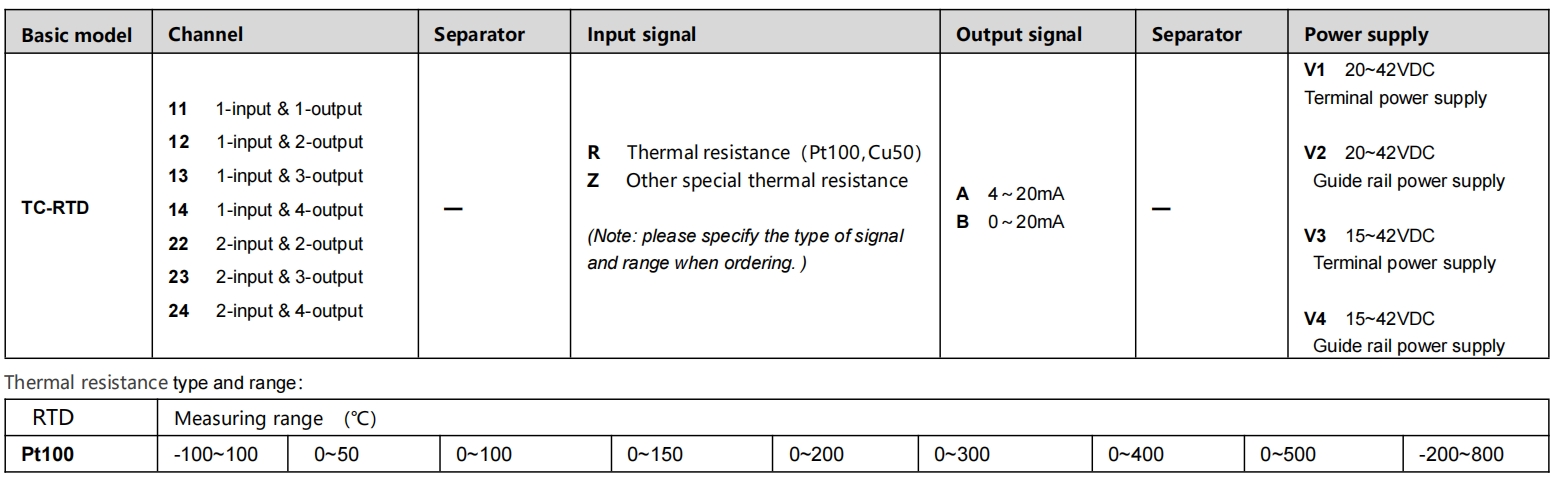
■ Model, model selection and ordering
Model selection example
Example 1. TC-RTD13-RA-V1 Pt100,0~200……1-input & 3-output,Thermal resistance converter(Pt100,0~200℃ input , 4~20mA output ,terminal power supply 20~42VDC)
Example 2. TC-RTD11-ZA-V2 Pt1000,-200~250……1-input & 1-output,Thermal resistance converter(Pt1000 , -200~250℃ input , 4~20mA output ,guide rail power supply 20~42VDC)
Note: if you select products with guide rail power supply, please order the special power supply DIN guide rail as well.
Optional accessories: Special power supply DIN guide rail (1 m/pc) PSDR-9000
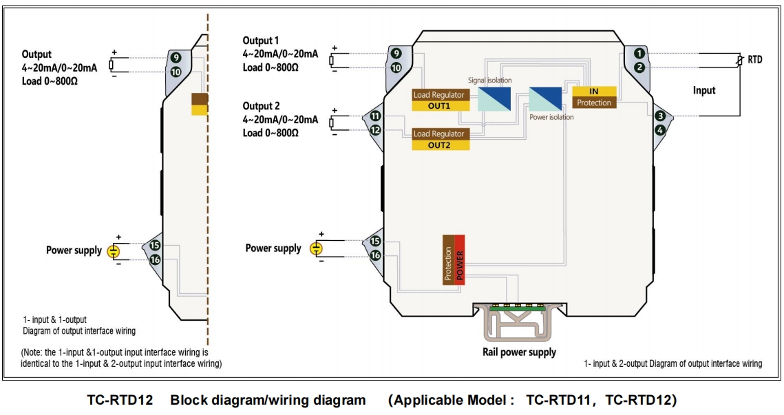
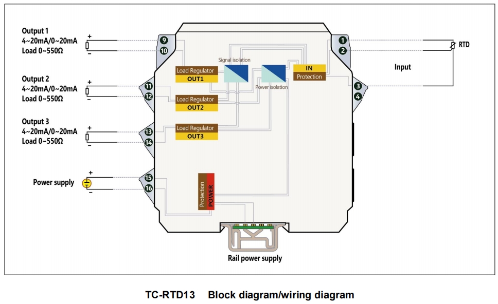
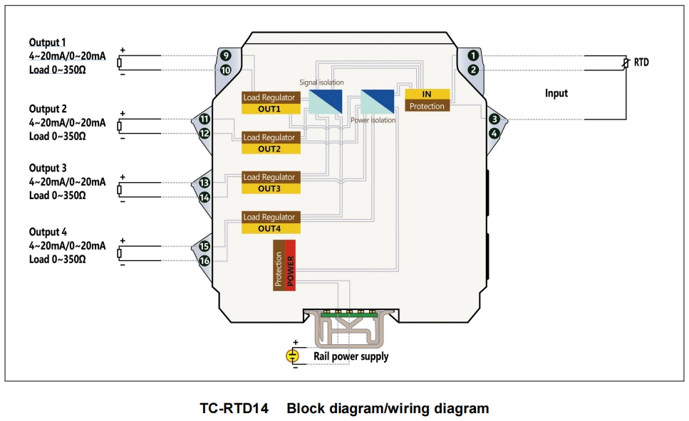
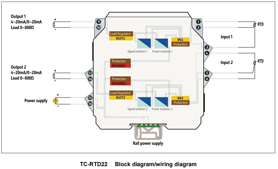
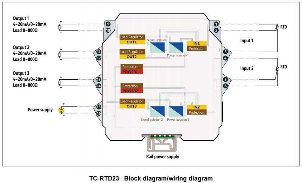
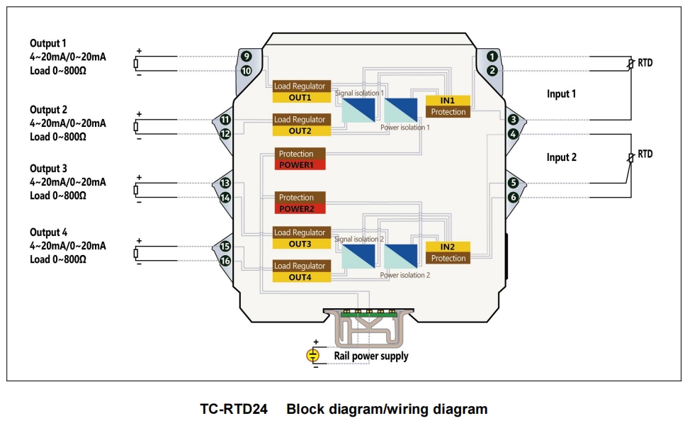
■ Block diagram/wiring diagram