■ Overview
TC-TESU signal isolator achieve conversion for all non-standard signals by simply switching the internal circuits. But definitions and indications in the column of the following “Model - model selection and ordering” need to be followed when placing an order. As for non-standard models that are not included in the scope of following models, you can customize the model when placing an order, but confirmation of the two parties is required.
TC-TESU models exclude resistance signal input. Resistance signal input in the universal signal isolator TC-TP11 can be selected instead. In actuality, most non-standard input signals in the following models can be replaced by TC-TP11. But TC-TP11 only includes the two output forms of 0~20 mA and 4~20 mA. Therefore, useful functions of TC-TESU mainly focus on non-standard output signal. Except for -10 V ~ +10 V output signal, other current output signals can be supplied by means of external power supply.
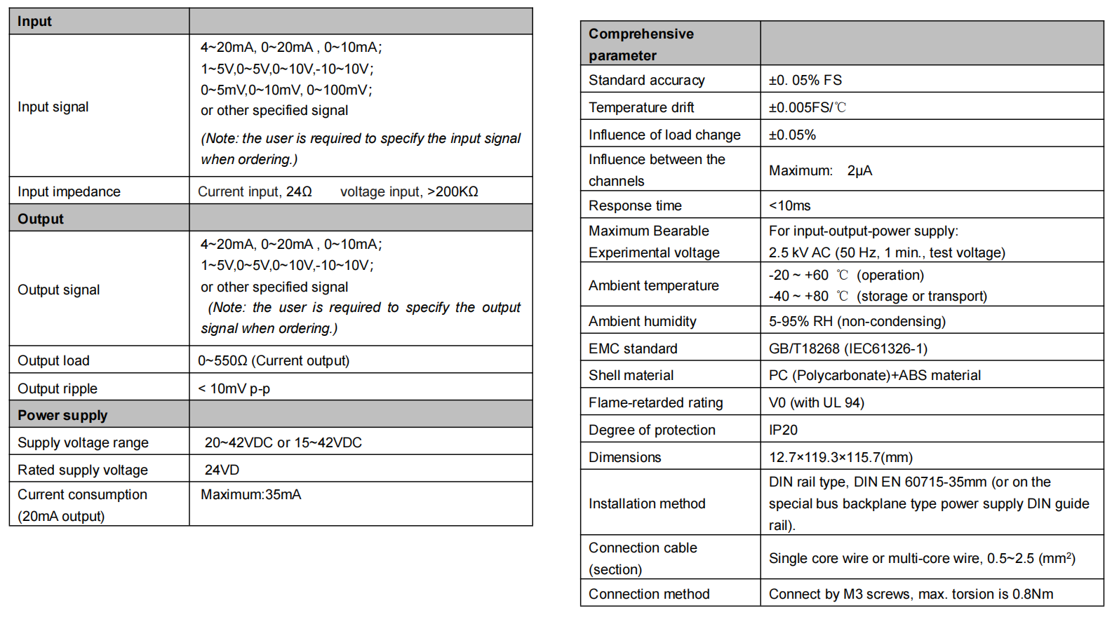
Accuracy ±0.05% FS, temperature drift: typical value < ±0.005 FS/℃.
Current input impedance is 25Ω. Voltage input impedance>200KΩ.
The current output load range is 0-550 Ω, Output voltage internal resistance ≤500Ω.
See the “Technical Data Sheet” in the specifications for current consumption or other functional indices.
There is no power light on the instrument panel. The power supply indicator is replaced by a model printed on the instrument panel. After the power is on, the model on the panel becomes illuminated by means of the LED backlight.
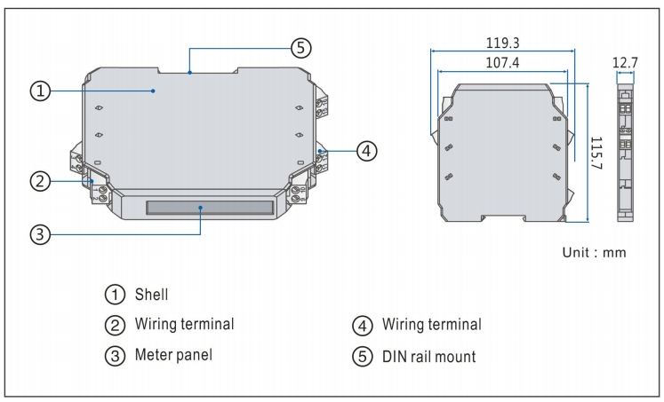
Clamping type structure, a 35 mm DIN standard guide rail clamping type installation is used. Screw terminal, the wire is connected and fastened by M3 screws.
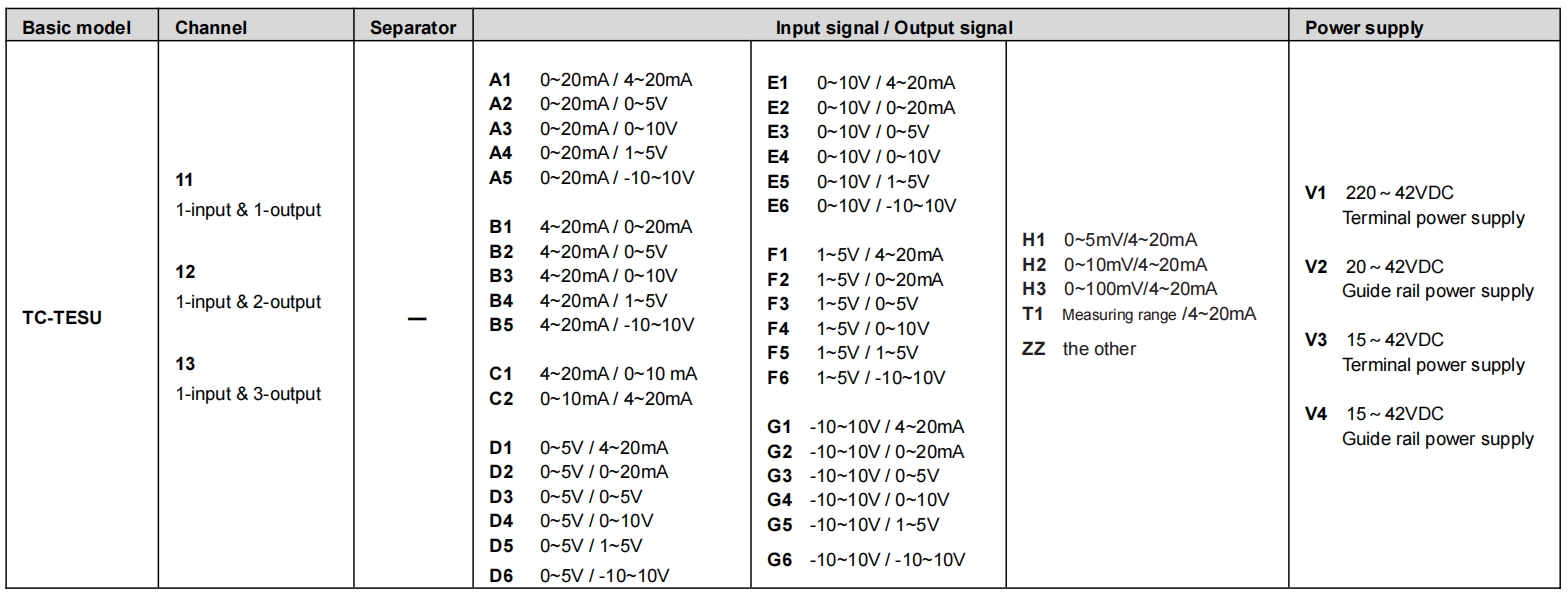
■ Model, model selection and ordering
Model selection example:
Example 1: TC-TESU11-E4-V1 ……Special signal isolator(0~10V input,0~10V output, Terminal power supply 20~42VDC)
Example 2: TC-TESU11-B3-V2 ……Special signal isolator(4~20mA input,0~10V output,guide rail power supply 20~42VDC)
Note: if you select products with guide rail power supply, please order the special power supply DIN guide rail as well.
Optional accessories:Special power supply DIN guide rail (1 m/pc) PSDR-9000
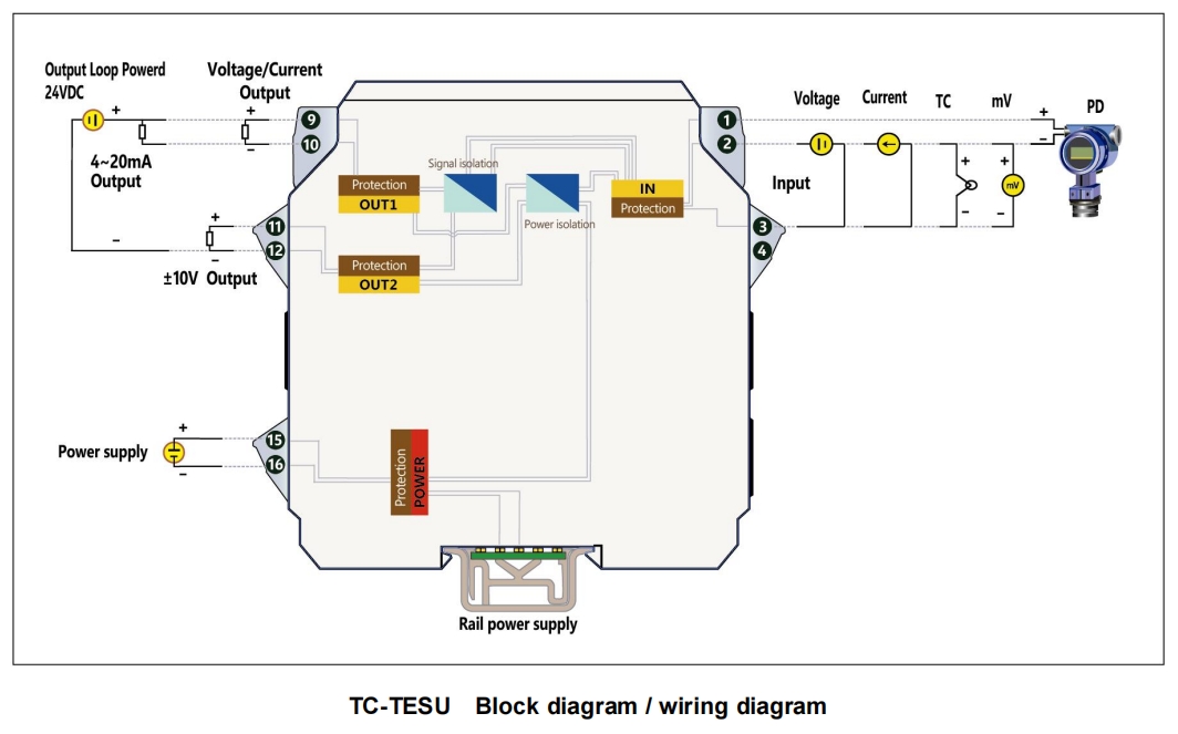
■ Block diagram/wiring diagram