TC-DI Switch or Proximity Switch Isolator

Comprehensive parameter:
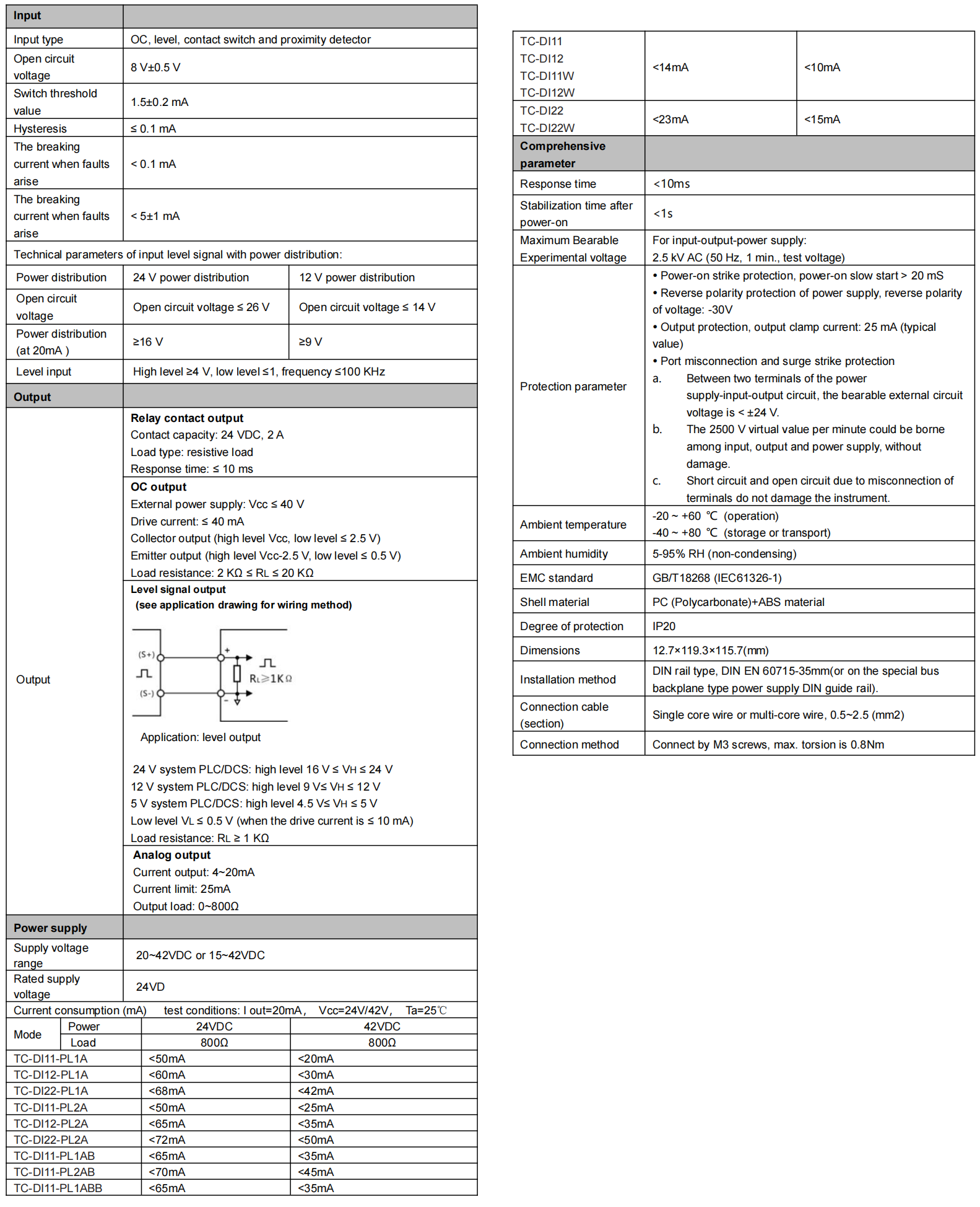
- Response time: <10ms
- Stabilization time after power-on: <1s
- Maximum Bearable Experimental voltage: For input-output-power supply: 2.5 kV AC (50 Hz, 1 min., test voltage)
Protection parameter: - Power-on strike protection, power-on slow start > 20 mS
- Reverse polarity protection of power supply, reverse polarity of voltage: -30V
- Output protection, output clamp current: 25 mA (typical value)
- Port misconnection and surge strike protection
- a. Between two terminals of the power supply-input-output circuit, the bearable external circuit voltage is < ±24 V.
- b. The 2500 V virtual value per minute could be borne among input, output and power supply, without damage.
- c. Short circuit and open circuit due to misconnection of terminals do not damage the instrument.
Ambient temperature:
- -20 ~ +60 °C (operation)
- -40 ~ +80 °C (storage or transport)
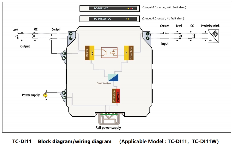
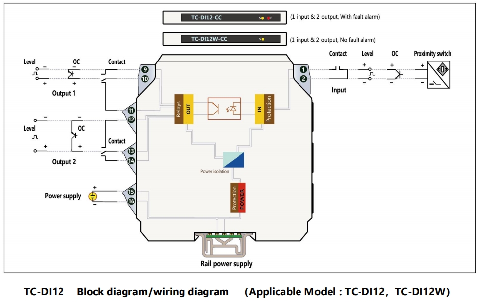
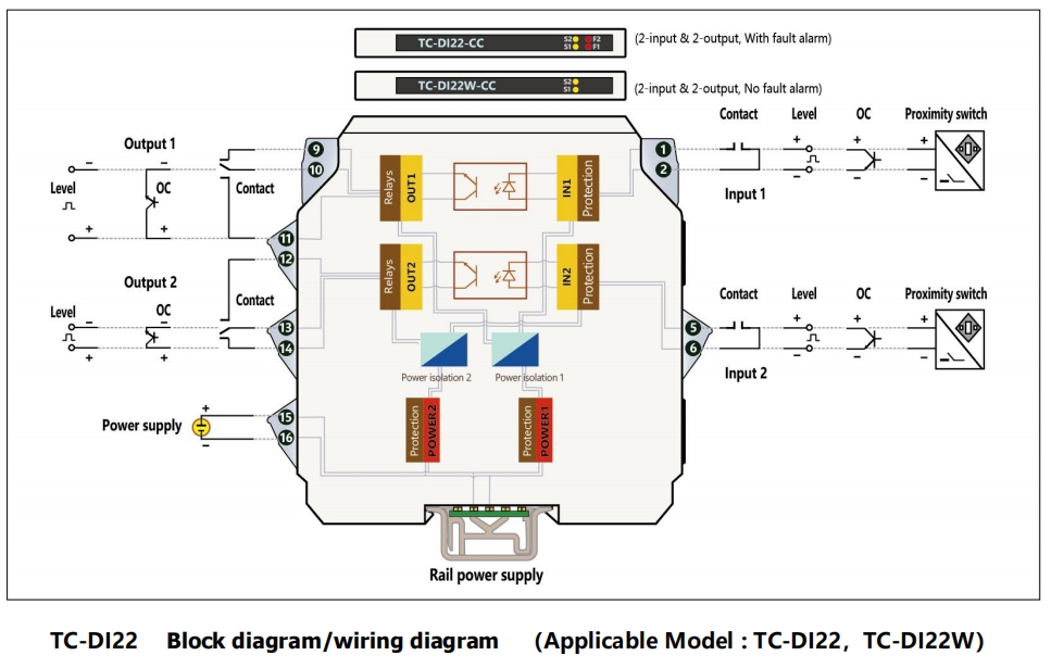
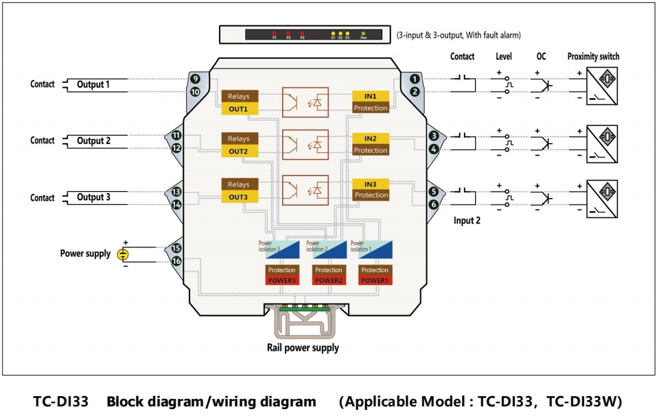
TC-DI applies to OC, level, contact switch or NAMUR proximity switch input. After being isolated, output as relay contacts (or OC output and level output).
Category:
Keywords:
Product Details

■ Overview
TC-DI applies to OC, level, contact switch or NAMUR proximity switch input. After being isolated, output as relay contacts (or OC output and level output).
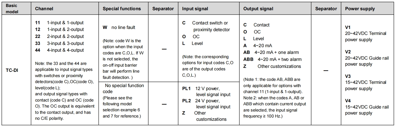
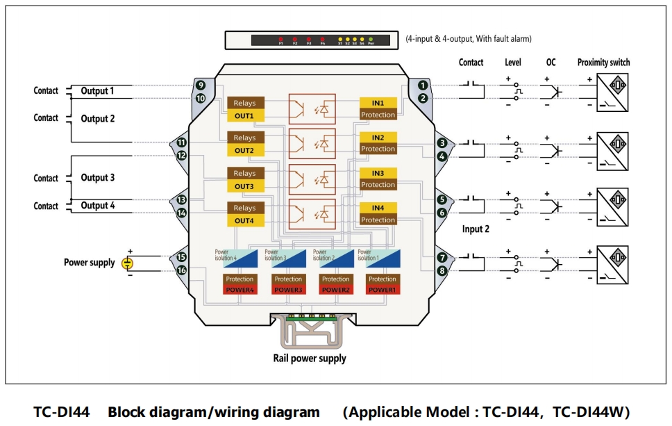
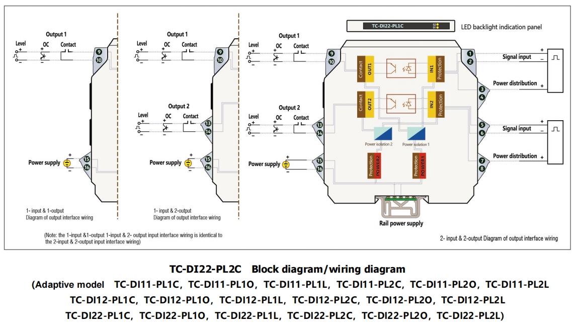
Basic channel forms of input and output includes 1-input and 1-output ,1-input and 2-output, 2-input and 2-output, 3-input and 3-output and 4-input and 4-output.
Isolation among input, output and power supply, a virtual value of 2500 V per minute.
Input type: OC, level, contact and proximity detector (Note: the user is required to specify
the output type when ordering.)
Switch threshold value: 1.5 ± 0.2 mA. Input short circuit current: < 5 ± 1 mA. Open circuit voltage of input terminal: 8 V ± 0.5 V.
Output type: contact, level, OC output, current signals and contact alarm output. (Note: user is required to specify the output type when ordering.)
Reversal return difference: ≤ ±0.1 mA.
Power supply range can be chosen within the range of 20-42 VDC or 15-42 VDC.
See the “Technical Data Sheet” in the specifications for current consumption or other functional indices.
LED backlight design is used for panel of on-off input isolation guard grating. The model on the panel becomes illuminated by means of LED backlight. In addition, there is a LED indicator light on the panel. There is a signal output status indicator light (yellow) and wire fault alarm indicator light (red). If there is no need for a wire fault alarm, products in all models with suffix “W” shall be used (see the model selection and ordering sheet).
Fault state setting/working state setting/fault sensor description Fault:
Faults refer specifically to special situations that the proximity detector breaks down, open circuits or short circuits occur, or the connection wire between the input signal and the on-off input intrinsically safe isolator is in open circuit or short circuit.
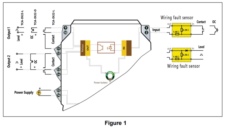
When the wire fault alarm is required, the fault signal sensor must be equipped between the OC, level and contact signals and TC-DI input terminal. Additionally, it shall be installed at front end of the remote wire to effectively check whether this connection wire has broken down (see Figure 1).
When faults occur, the fault alarm red light will come on. The output value will be mandatorily set as the specific set value corresponding to system safety. The set value is determined by the K4, K5 and K6 positions of the dial switch.
In a normal working state, whether the output value and the input value are of in-phase or anti-phase is determined by the K1, K2 and K3 positions of the dial switch. Once a fault occurs, the K1, K2 and K3 set values will be ineffective until troubleshooting.
Identified threshold value of the input sensor or the input connecting wire fault:
Open circuit of the input sensor or the input connecting wire; < 1.1 ± 0.1 mA
Short circuit of the input sensor or the input connecting wire; > 2.2 ± 0.1 mA (Note: the dial switch is set on the PCB board inside the instrument.)
Fault state setting:
When 2.2 ± 0.1 mA < input signal < 1.1±0.1 mA, the fault light (red) will be on.
If the fault light is on and the yellow light is on at the same time, this indicates that the contact has closed (default set value) in a faulty state. If the fault light is on while the yellow light is off, this indicates that the contact has not closed in a faulty state.
Whether the output contact closes or not in a faulty state is indicated in the order contract or set by K4, K5 and K6 of the dial switch (see Figure 2):
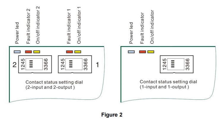
When K4 and K6 are switched on, the output relay will be closed in a faulty state (the yellow light will be on);
When K5 and K6 are switched on, output relay in a faulty state (the yellow light will be off).
Working state setting:
When 2.2±0.1 mA > input signal >1.1±0.1 mA and the fault light (red) is off, it is in a working state:
If the fault light (red) is off and the yellow light is on, this indicates that operation is in a fault-free state and contact is closed;
If the fault light (red) is off and the yellow light is off, this indicates that operation is in a fault-free state and contact is not closed;
Whether the output contact closes or not in a faulty state is indicated in the order contract or set by K1, K2 and K3 of the dial switch (see Figure 2):
When K1 and K3 are switched on and input is closed, the output relay will be contact closed (in-phase), the red light will be off and the yellow light on.
When K2 and K3 are switched on and input is closed, the output relay will not be contact closed (anti-phase), the red light will be off and the yellow light is off.
(Note: when the contact is closed, the corresponding input and output level is 0, the C and E electrode of the corresponding OC is in a saturated state, all of which are in a current sinking state.)
Fault sensor:
The fault sensor is unrelated to the proximity detector. The fault and normal states can be distinguished correctly without fault sensor.
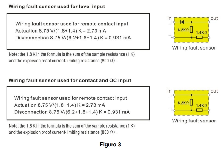
The fault sensors for OC, contact and level input signals are used to distinguish between on-off actions, caused by the connecting wire open circuit or short circuit and output in a normal working state. The on-off state of three input signals during normal operation is the same as that of the open circuit or short circuit during a connecting wire fault. If the corresponding fault sensors (see Figure 3) are not equipped, the output will maintain the same fault status values set by K4, K5 and K6, which cannot work properly. Thus, when selecting and using various models with wire fault alarms, the corresponding wire fault sensors must be used at the same time.
■ Model, model selection and ordering
Model selection example
Example 1. TC-DI11W-CC-V1……1-input & 1-output,no line fault alarm(switch contact or proximity detector input, and contact output, terminal power supply 20~42VDC)
Example 2. TC-DI22-CC-V2……2-input & 2-output, with line fault alarm(switch contact or proximity detector input , and contact output, guide rail power supply 20~42VDC)
Example 3. TC-DI44-CC-V1……4-input & 4-output, with line fault alarm(switch contact or proximity detector input , and contact output, terminal power supply 20~42VDC)
Example 4. TC-DI44W-CC-V2……4-input & 4-output,no line fault alarm(switch contact or proximity detector input , and contact output, guide rail power supply 20~42VDC)
Example 5. TC-DI11W-LL-V2……1-input & 1-output,no line fault alarm,without wire fault alarm(level signal input , and level signal output, guide rail power supply 20~42VDC)
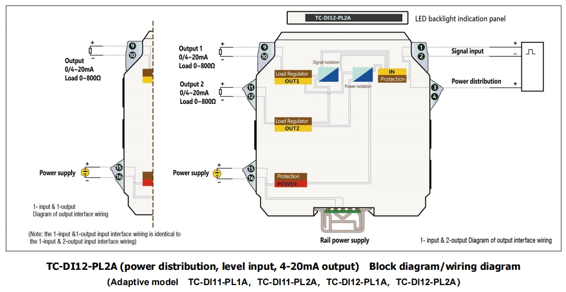
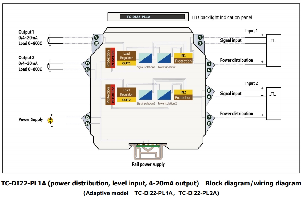
Example 6. TC-DI12-PL1A-V1……1-input & 2-output,(12V power distribution,level signal input,and two outputs of 4~20mA, terminal power supply 20~42VDC)
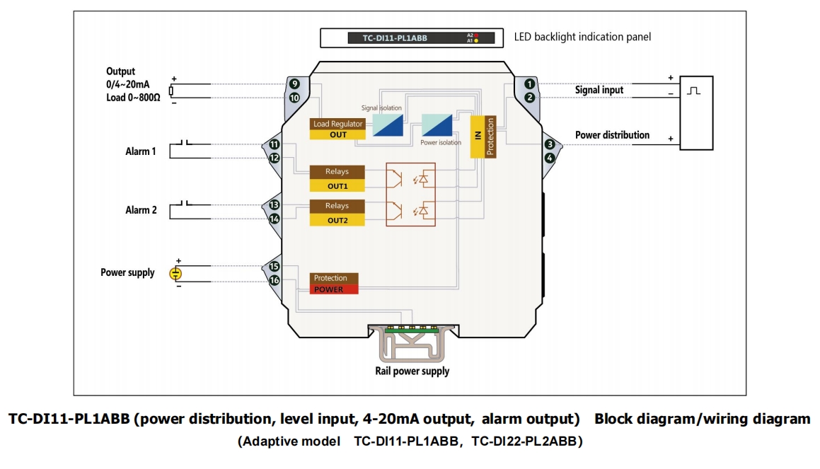
Example 7. TC-DI11-PL2ABB-V1……1-input & 1-output,(24V power distribution,level signal input,,output of 4~20mA and two relay contact alarm outputs,
terminal power supply 20~42VDC)
Note: if you select products with guide rail power supply, please order the special power supply DIN guide rail as well.
Optional accessories: Special power supply DIN guide rail (1 m/pc) PSDR-9000
■ Block diagram / wiring diagram
■ Technical Data
Related Application
Hot Products
Address:No. 41 Chengxi Road, Yantan Industrial Park, Zigong, Sichuan Province, China
E-mail:sales@vacorda.com
Copyright © 2024 Sichuan VACORDA Instruments Manufacturing Co., Ltd.


