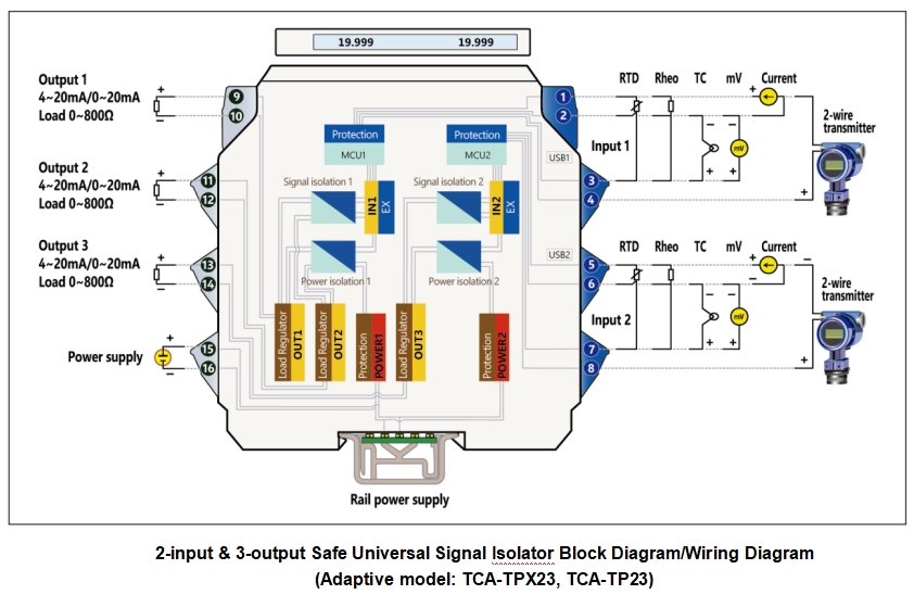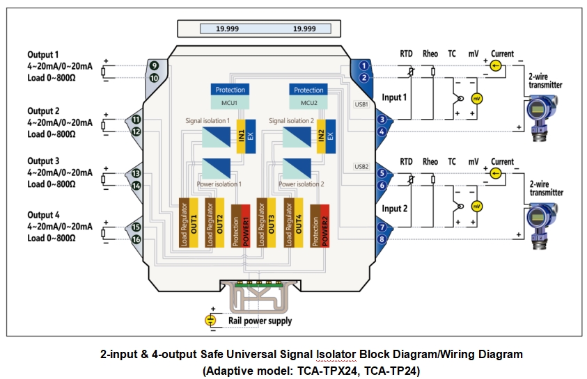
TCA-TP is an intrinsically safe instrument for signal transmission, connecting various sensors and actuators in dangerous areas. After isolation, it transmits and outputs the standard current signals to control systems or other instruments in safe areas. This series of products can thoroughly and accurately ensure that signals on site achieve high voltage electric isolation from connecting devices; the connection with the property of zero current or zero potential difference can come into being among system power sources, input signals and output signals; and the accuracy of signal transmission can be ensured, with the complexity of wiring technology for ground wires and its costs minimized. It is also capable of preventing hazardous energy being fed to sites with flammable gases by means of switching circuits, maintaining the safety explosion-proof grade of signal sites.
The safe universal signal isolator switches signal inputs such as power distribution, current, thermocouple, thermal resistance, millivolt and sliding resistance in various wiring modes. Input signals can complete the configuration settings by means of the calibration software and interfaces (accessories optional). Configuration parameters only include three items, i.e. signals (or graduation), null point and full scale, which can be conducted in the state of no power. The accuracy after normal use is greater than 0.03%FS. Input is open circuit or short circuit, the output is above the high limit or below the low limit, the default value of the configuration is output greater than 22mA. The configuration can also be reset.
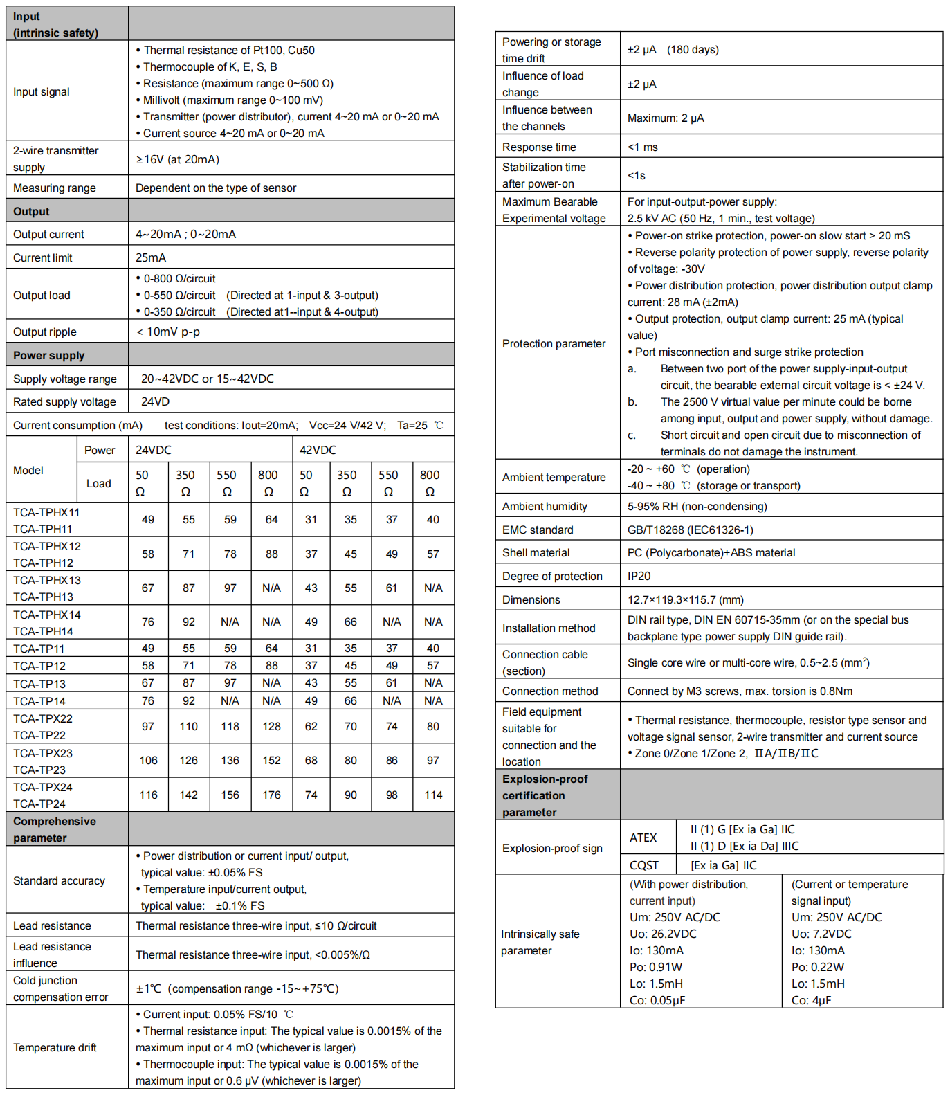
Thermal resistance input range: 10 Ω~400 Ω; minimum resolution: ±2 mΩ; stability: ±3 mΩ. When the compensating lead error of three-wire input is not less than 50 ℃ range (Pt100), the additive error is not more than ±0.02 ℃.
Thermocouple input voltage range: 4~80 mV; minimum resolution: ±1 μV; stability: ±2 μV. The additive error of cold junction compensation is not more than ±1 ℃.
The maximum range of the sliding resistance is 0~500Ω. When the range is less than 50Ω, the three-wire form should be used for connections. Input mode offsets the lead error. Accuracy ±0.05% FS
The maximum range of DC millivolt should be 0~100mVDC, and the minimum should be 0~5mVDC, with the accuracy of ±0.05%FS. Minimum resolution: 1μV; stability: 2μV; temperature drift: ±20PPM/℃.
The power distribution voltage is more than 16VDC. The power distribution output clamp current can be customized as required, but must be specified upon ordering. The factory default is 28 mA (±2mA).
For power distribution or current input/output, the typical accuracy value is ±0.05% FS; and the temperature drift is ±0.1 μA/℃.
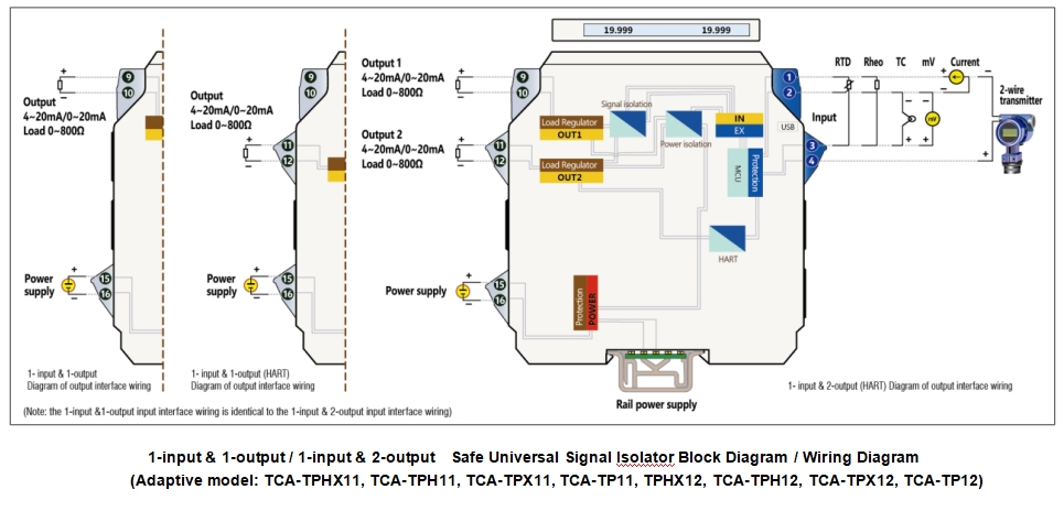
The output signal can be extended from 4~20 mA to 0~20 mA.
The output self-adaptive load is 0-800 Ω
The power supply range can be chosen from within range of 20~42VDC or 15~42VDC.
See the “Technical Data Sheet” in the specifications for current consumption or other functional indices.
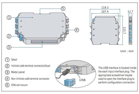
The instrument panels for safe universal signal isolators include two types: LCD and LED backlight. The LCD can display the input value, output value, or the position number required by the user. In case of no LCD, the LED backlight design shall be used for the instrument panel. After the power is on, the model on the panel becomes illuminated by means of the LED backlight.
Clamping type structure, a 35 mm DIN standard guide rail clamping type installation is used. Screw terminal, the wire is connected and fastened by M3 screws.
- Model, model selection and ordering
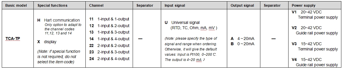
Model selection example
Example 1. TCA-TP11-UB-V1.…1-input & 1-output, intrinsically safe universal signal isolator (user must set parameters:with power distribution, 0-20mA input, 0-20mA output.
Terminal power supply 20-42VDC)
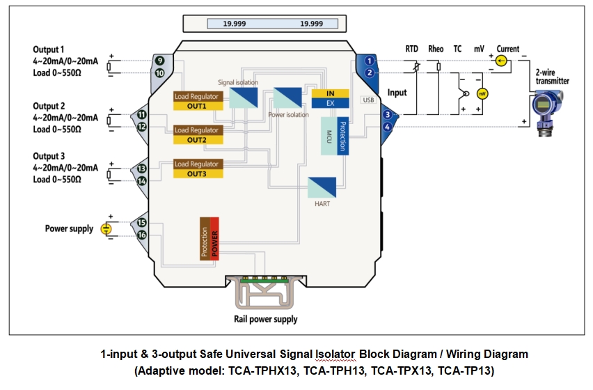
Example 2. TCA-TPHX13-UA-V1…..1-input & 3-output, intrinsically safe universal signal isolator, Hart communication, with displays (user must set parameters:4-20mA input, 4-20mA output.
Terminal power supply 20-42VDC)
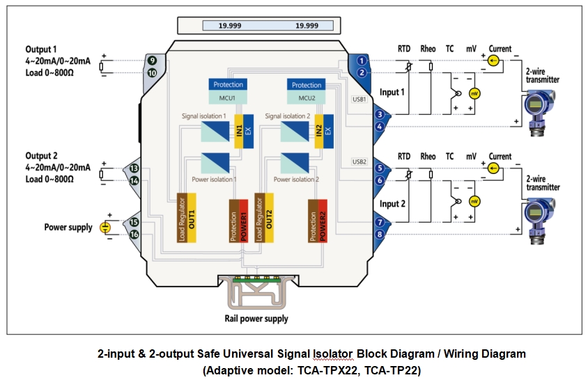
Example 3. TCA-TPX22-UA-V2…..2-input & 2-output, intrinsically safe universal signal isolator, with displays (user must set parameters: Pt100, 0-300℃ input, 4-20mA output.
Guide rail power supply 20-42VDC)
Note: if you select products with guide rail power supply, please order the special power supply DIN guide rail as well.
Optional accessories: Calibrated software CRFW-2000 for winXP and win7 PC
Calibration interface CR-2206 for general products
General product Android calibration interface FAIF-1904
Special power supply DIN guide rail (1 m/pc) PSDR-9000