■ Overview
TCA-AO-PI is a combination of output-type intrinsically safe isolator and input-type intrinsically safe isolator. It is applicable to the uniform processing of single circuit control signals. Wherein: “AO” refers to output intrinsically safe isolator channel. “PI” refers to input channel with power distribution 4~20 mA input or 4~20 mA current supply signal. Their features are consistent with the corresponding output and input intrinsically safe isolator respectively. “AO” transmits 4~20 mA analog signals to the field actuator and other equipment; “PI” receives 4~20 mA signals input from the field transmitter and other equipment or 4~20mA single signals. The two are all intrinsically safe signals, which are isolated from input signals and floating over the ground potential.
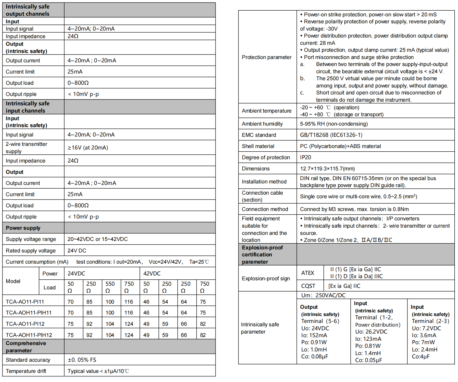
Accuracy ±0.05% FS Temperature drift (typical value) <±1μA/10 ℃. -20 - +80 ℃ temperature test, typical value < ±10 μA.
The test preheating time is 0.
Output current signal: 4~20 mA can be extended to 0~20 mA.
Output self-adaptive load: 0~800 Ω. High limit of the output current is 25 mA. Load change error < ±2 μA/800 Ω; impact of load open circuit on the other output < ±2 μA.
The power supply range can be chosen within the range of 20~42 VDC or 15~42 VDC.
See the “Technical Data Sheet” in the specifications for current consumption or other functional indices.
There is no power light on the instrument panel. The power supply indicator is replaced by a model printed on the instrument panel. After the power is on, the model on the panel becomes illuminated by means of the LED backlight.
Clamping type structure, a 35 mm DIN standard guide rail clamping type installation is used. Screw terminal, the wire is connected and fastened by M3 screws.
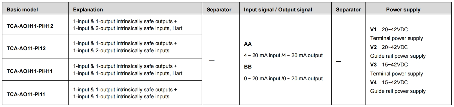
■ Model, model selection and ordering
Model selection example
Example 1. TCA-AOH11-PIH11-AA-V1 ……1-input & 1-output,Intrinsically safe isolating driver & intrinsically safe power distribution or current signal isolator,
HART communication(4~20mA input,4~20mA output,terminal power supply 20~42VDC)
Example 2. TCA-AO11-PI11-AA-V1 ……1-input & 1-output,Intrinsically safe isolating driver & intrinsically safe power distribution or current signal isolator
(4~20mA input,4~20mA output,terminal power supply 20~42VDC)
Example 3. TCA-AO11-PI12-AA-V2……1-input & 1-output,Intrinsically safe isolating driver &1-input & 2-output,intrinsically safe power distribution or current signal isolator
(4~20mA input,4~20mA output, guide rail power supply 20~42VDC)
Note: if you select products with guide rail power supply, please order the special power supply DIN guide rail as well.
Optional accessories: Special power supply DIN guide rail (1 m/pc) PSDR-9000
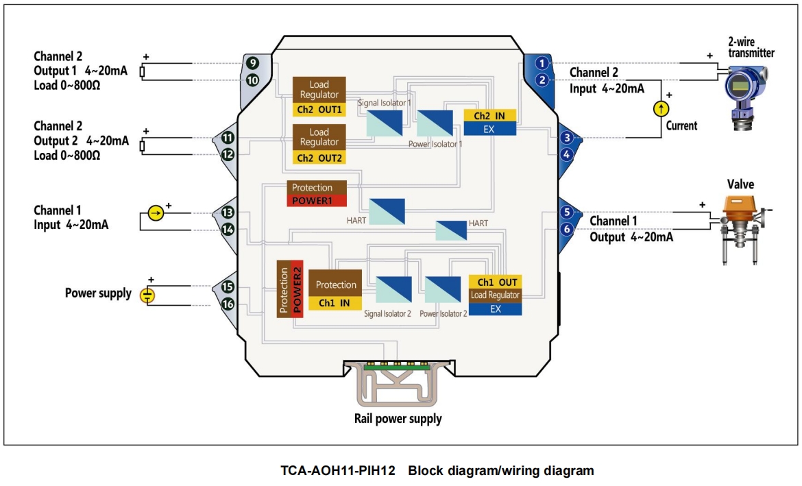
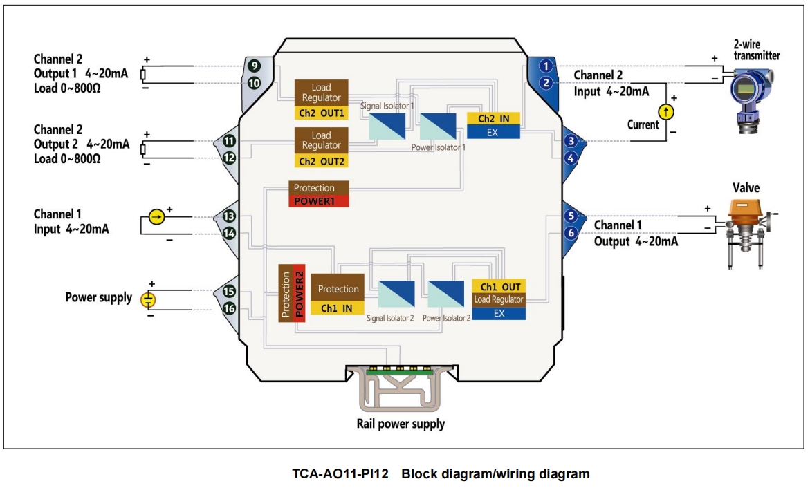
■ Block diagram/wiring diagram