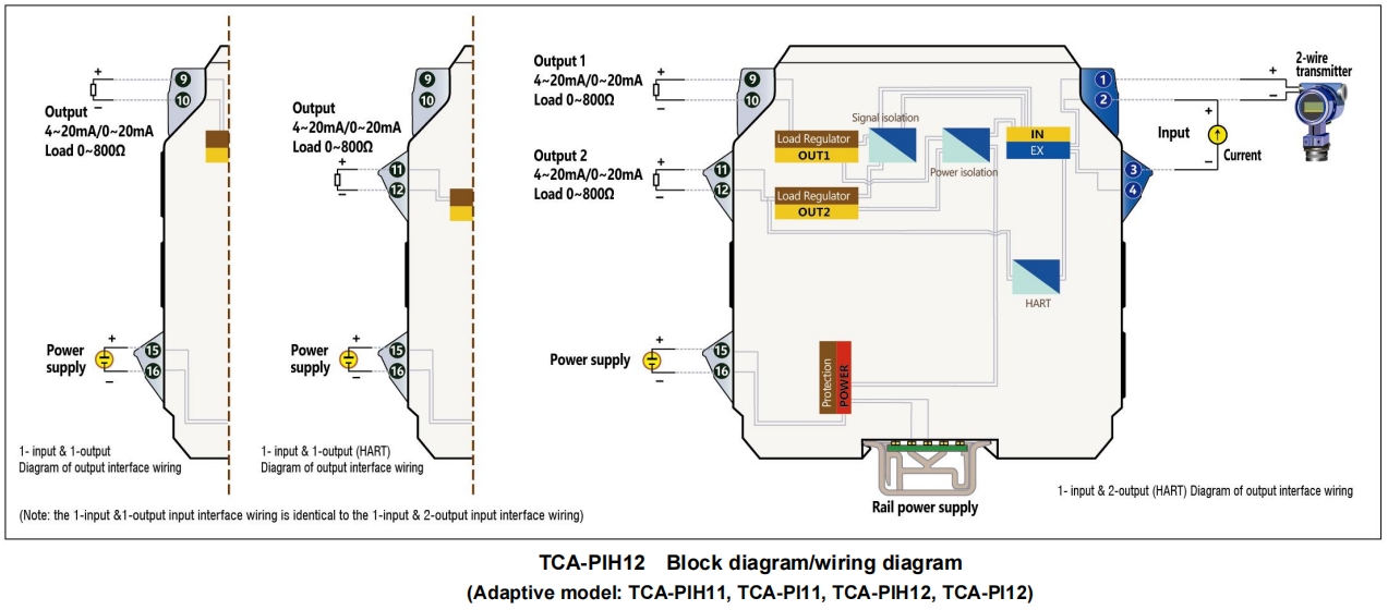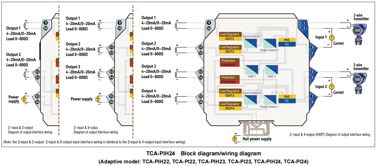
TCA-PI applies to supplying isolated DC to transmitters in hazardous area and accepting current signal input from the transmitter. It can also accept current supply signal input independently. After isolation, interference suppression and other processing, it outputs current signals to control systems or other instruments in safe areas.
Support passing of HART (optional)
Basic channel forms for input and output include 1-input and 4-output, 2-input and 4-output and 3-input and 3-output. They can be derived as 1-input and 1-output, 1-input and 2-output, 1-input and 3-output, 2-input and 2-output and 2-input and 3-output.
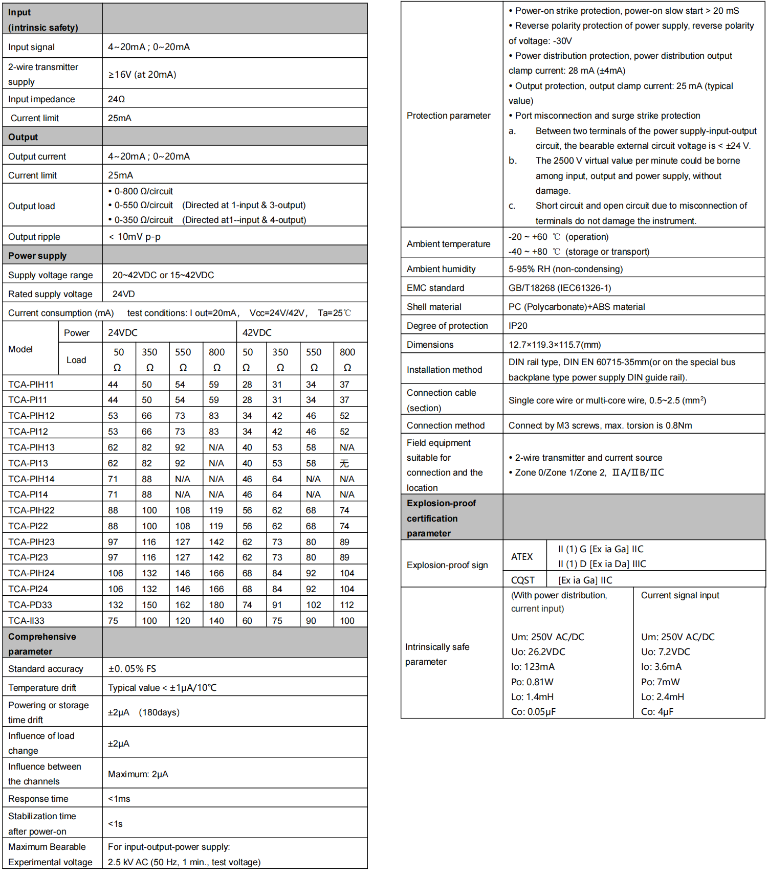
The power distribution voltage is more than 16VDC. The power distribution output clamp current can be customized as required, but must be specified when ordering. The factory default value is 28 mA (±4 mA).
Input current signal: 4~20 mA or 0~20 mA.
Output current signal: 4~20 mA or 0~20 mA.
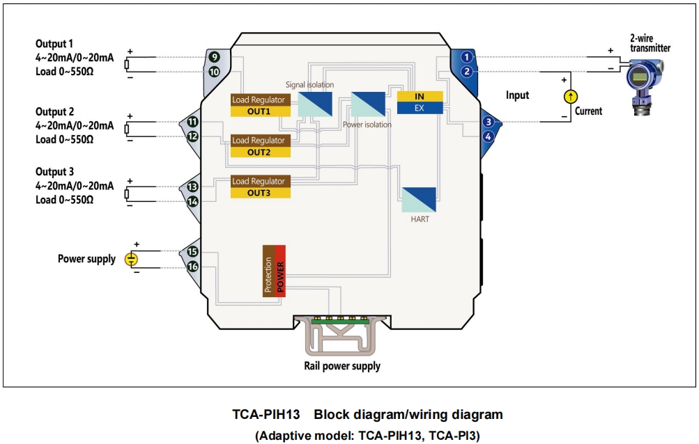
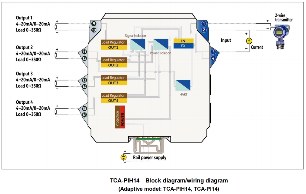
Output self-adaptive load is 0~800 Ω (Note: 1-input & 3-output load is 0~550 Ω, and 1-input & 4-output load is 0~350 Ω).High limit of the output current is 25 mA. Load change error < ±2 μA/800 Ω; impact of load open circuit on the other output < ±2 μA. (Among multiple outputs, if one output is not used, its output terminals shall be in short circuit for 0 Ω load. Working current makes the power supply current fall to 0 Ω of load).
Accuracy ±0.05% FS Temperature drift (typical value) < ±1 μA/10 ℃. -20~+80 ℃ baking oven experiment, typical value < ±10 μA.
The test preheating time is 0.
The power supply range can be chosen from within range of 20~42VDC or 15~42VDC.
See the “Technical Data Sheet” in the specifications for current consumption or other functional indices.
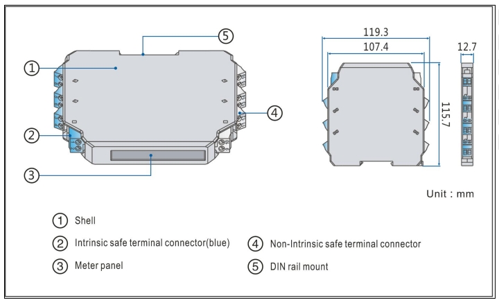
There is no power light on the instrument panel. The power supply indicator is replaced by a model printed on the instrument panel. After the power is on, the model on the panel becomes illuminated by means of the LED backlight.
Clamping type structure, a 35 mm DIN standard guide rail clamping type installation is used. Screw terminal, the wire is connected and fastened by M3 screws.
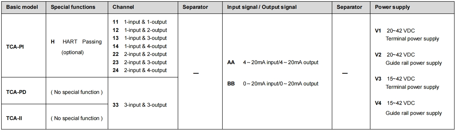
■ Model, model selection and ordering
Model selection example
Example 1. TCA-PIH12-AA-V1…..1-input & 2-output,Intrinsically safe power distribution or current signal isolator,HART(4~20mA input,4~20mA output , terminal power supply 20~42VDC)
Example 2. TCA-PI11-AA-V1…….1-input & 1-output,Intrinsically safe power distribution or current signal isolator(4~20mA input,4~20mA output,terminal power supply 20~42VDC)
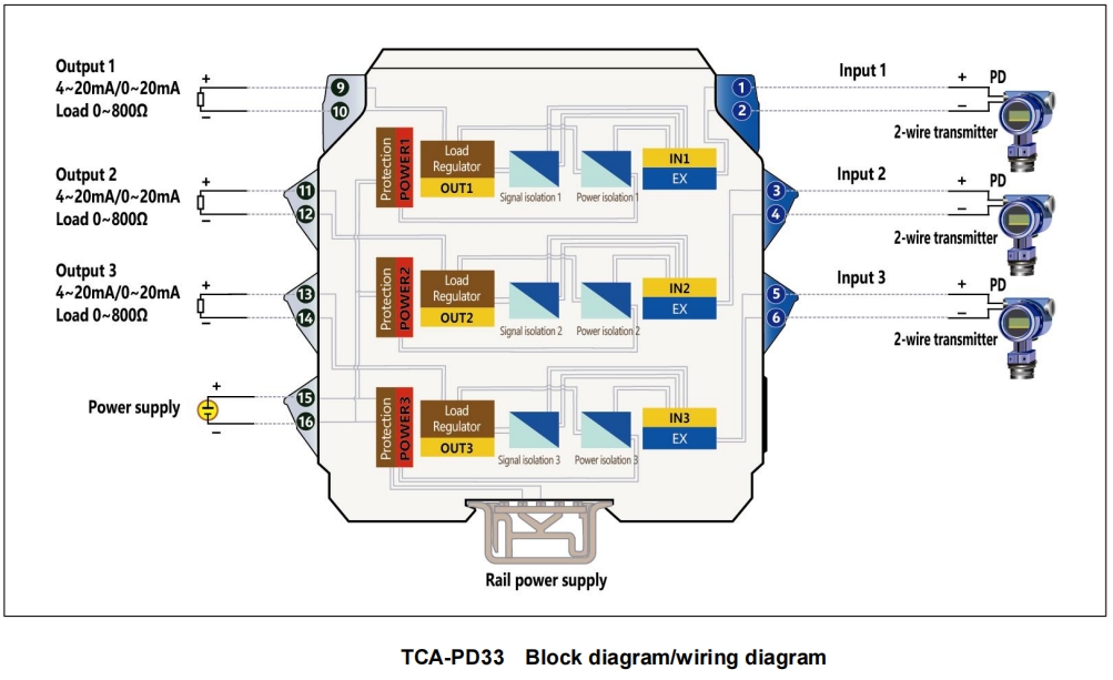
Example 3. TCA-PD33-AA-V1……3-input & 3-output,Intrinsically safe power distribution isolator(4~20mA input,4~20mA output,terminal power supply 20~42VDC)
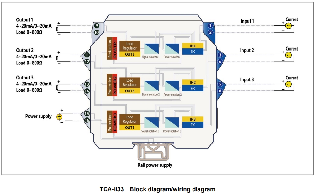
Example 4. TCA-II33-BB-V2……...3-input & 3-output,Intrinsically safe current signal isolator(0~20mA input,0~20mA output,guide rail power supply 20~42VDC)
Note: if you select products with guide rail power supply, please order the special power supply DIN guide rail as well.
Optional accessories: Special power supply DIN guide rail (1 m/pc) PSDR-9000
■ Block diagram/wiring diagram